To extend the Pi, we are using breakout boards that connect to the PI using a standard communication bus I2C. StemmaQT and Qwiic use a standardized 4-pin connector to connect devices using the I2C protocol.
The StemmaQT and I2C parts often have a fixed I2C address; to differentiate between similar parts, the devices often have pads that allow additional bits to be pulled high or low. The addresses are in hexidecimal format, things like 0x6f. This is the hexadecimal (or hex) representation for the decimal number 111 which is represented as 1101111 in binary. You are not expected to make any kinds of conversions but should have some conceptual grasp that a hex value is just a number shown another way. This Python library will assist you if you need help manipulating hexidecimal numbers.
The buttons you've used on the screen are quite simple. Aside from debouncing, when you press down you are closing a circuit, allowing electricity flow to the pins wired to the two buttons, in this case GPIO 23 and 24. That's a perfectly reasonable way to connect a button. I2C is not typically used for buttons but here, we demonstrate one way you might see it. This also allows additional functionality to be built right into the button, such as the ability to remember the last time it was pressed.
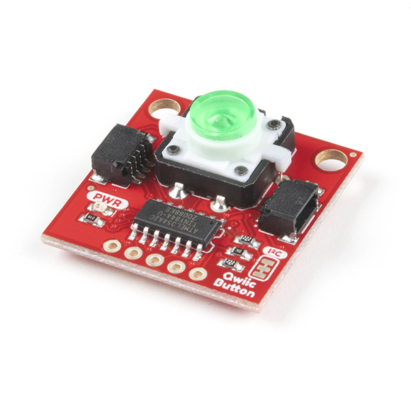
From your kit, take out the mini-PiTFT, a stemmaQT cable and the Qwiic Button.
Connect the one side of cable to the StemmaQT port on the underside of the PiTFT screen. It will only fit in one way, it should not require much force.
As before, connect to your Pi and activate your virtual environment.
ssh pi@ixe00
pi@ixe00:~ $ source circuitpython/bin/activate
(circuitpython) pi@ixe00:~ $
On the pi, Navigate to your interactive lab hub, pull changes from upstream, and install new packages. If you have merge conflicts, you need to resolve them. If you've never done this before ask people in your group for help.
(circuitpython) pi@ixe00:~$ cd Interactive-Lab-Hub
(circuitpython) pi@ixe00:~/Interactive-Lab-Hub $ git remote add upstream https://github.com/FAR-Lab/Interactive-Lab-Hub.git
(circuitpython) pi@ixe00:~/Interactive-Lab-Hub $ git pull upstream Fall2022
(circuitpython) pi@ixe00:~/Interactive-Lab-Hub $ git add .
(circuitpython) pi@ixe00:~/Interactive-Lab-Hub $ git commit -m "merge"
(circuitpython) pi@ixe00:~/Interactive-Lab-Hub $ git push
(circuitpython) pi@ixe00:~/Interactive-Lab-Hub $ cd Lab\ 2/
(circuitpython) pi@ixe00:~/Interactive-Lab-Hub/Lab 2 $ pip install -r requirements.txt
This class uses a lot of material that is developed with the intention of being free, open and accessible. All of the parts you used for this lab openly post their code and schematics should others want to riff on these designs or learn how they work. You are encouraged to take a look. You may find that someone has solved your problems for you and neatly packed them in a library. Feel free to look at and use solutions that others have posted so long as you always cite their contributions.
To demonstrate the button we are using this CircuitPython library. You can also try this Sparkfun Library which has slightly simpler syntax. The devices and sensors in your kit have libraries that will allow you to integrate them with your Pi using python. They also provide examples of usage. If you are unsure about how to use something, look at its documentation then ask your TAs.
Try running python library_example.py.
Some important things to note from the code:
- We create an I2C device to handle communication with the pi.
- We then scan for devices on the bus.
- We check if
default_addr = 0x6fis listed in the found devices. This is the address your button comes programmed with, you can also change this and have it store the update on the button. - Once we initialize the I2C_Button object the rest of the code shows us some of the builtin capabilities.
The chances are that running python library_example.py works for a few seconds, before it returns 'OSError: [Errno 121] Remote I/O error'. This problem has to do with the I2C baudrate setting. If you run into this problem, you need to edit the /boot/config.txt file by typing:
sudo nano /boot/config.txt
- Search for where it says
dtparam=i2c_arm=on, add a line beneath that that saysdtparam=i2c_arm_baudrate=10000. - If your
dtparam=i2c_arm=onis commented out with a#, remove the#in front ofdtparam=i2c_arm=on. - Save the file and reboot your Pi with
sudo shutdown -r now.
After rebooting, python library_example.py should work. If it seems to glitch the first time, exit the script with Ctrl+C and run the same command again.
Run the file I2C_scan.py and the output should look like:
(circuitpython) pi@ixe00:~/Interactive-Lab-Hub/Lab 2 $ python I2C_scan.py
I2C ok!
I2C addresses found: []
Now plug the other end of the cable into the ports on the right of the button board. The pwr LED should turn on. Run the file again and you should see the device ID. You can also try daisy chaining multiple devices and sensors and running again.
(circuitpython) pi@ixe00:~/Interactive-Lab-Hub/Lab 2 $ python I2C_scan.py
I2C ok!
I2C addresses found: ['0x6f']
With I2C devices we can read the registers directly with button_registers.py. Run the command to see what the current registers for the button are. You can look here to try and figure out what the output means.
Use a higher level device interface can make reading and writing registers for I2C devices easier. Try running button_device.py and pressing the button. Look at the code and the list of registers and see if you can figure out what line 56 is for.
56 write_register(device, STATUS, 0)
The more buttons the merrier! ...but how do you control them individually when they are come with the same default I2C address 0x6f?
Option 1 - Software: Look into the list of registers of the buttons again, is it possible to change the I2C address through software progrmming?
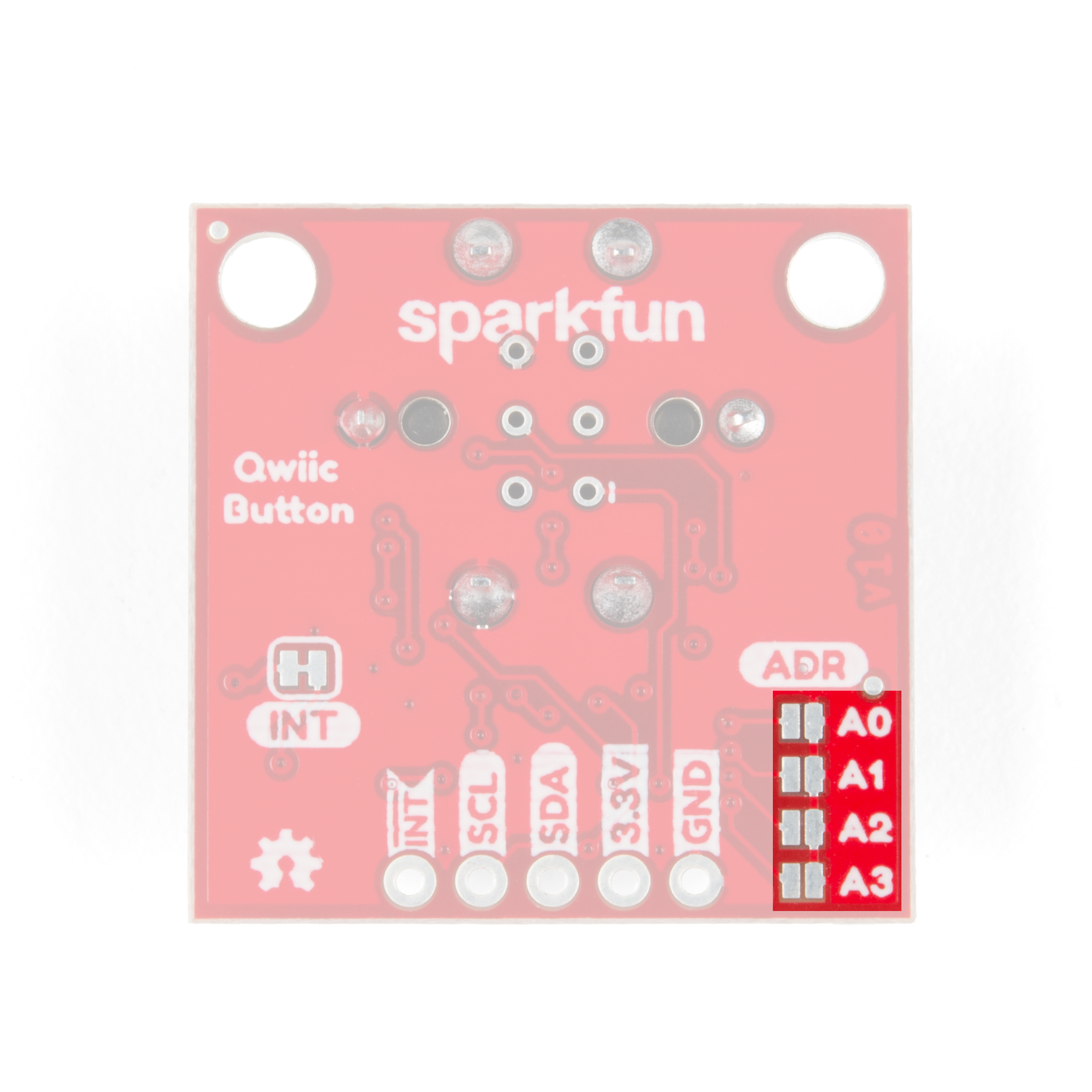
Option 2 - Hardware: Look at the bottom right corner of the back of the button, you should be able to local a sign of ADR with A0 - A3 jumpers. By solding these I2C address jumpers, you can actually change the address directly! Check here to see how the I2C address change!
Your kit is full of sensors! Look up what they can do and feel free to ask your TAs, we love to talk sensors. We will go further in depth into sensors in the coming weeks, but we put this small sample here to demonstrate how you can get sensor data if you want to use it for your project this week.
We are going to connect the Adafruit APDS9960 Proximity, Light, RGB, and Gesture Sensor. You can leave the button plugged in and daisy-chain the sensor, this is part of the magic of I2C.
Now run python proximity.py. What did you see? Check out here to learn more about the sensor and think about how you might be able to apply it in the future projects!


