Powering halogen bulb #1882
Replies: 16 comments
-
|
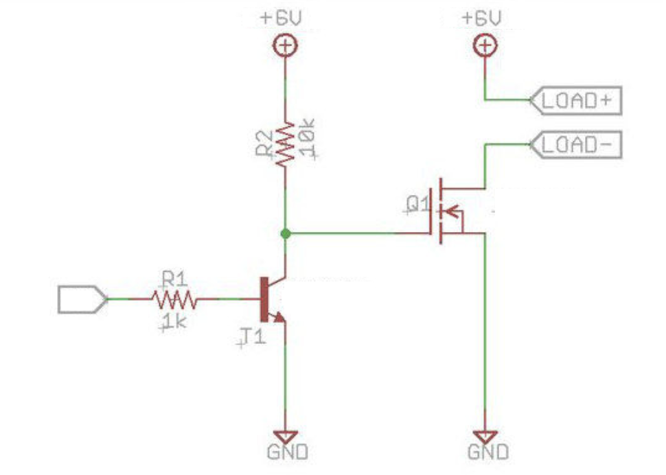
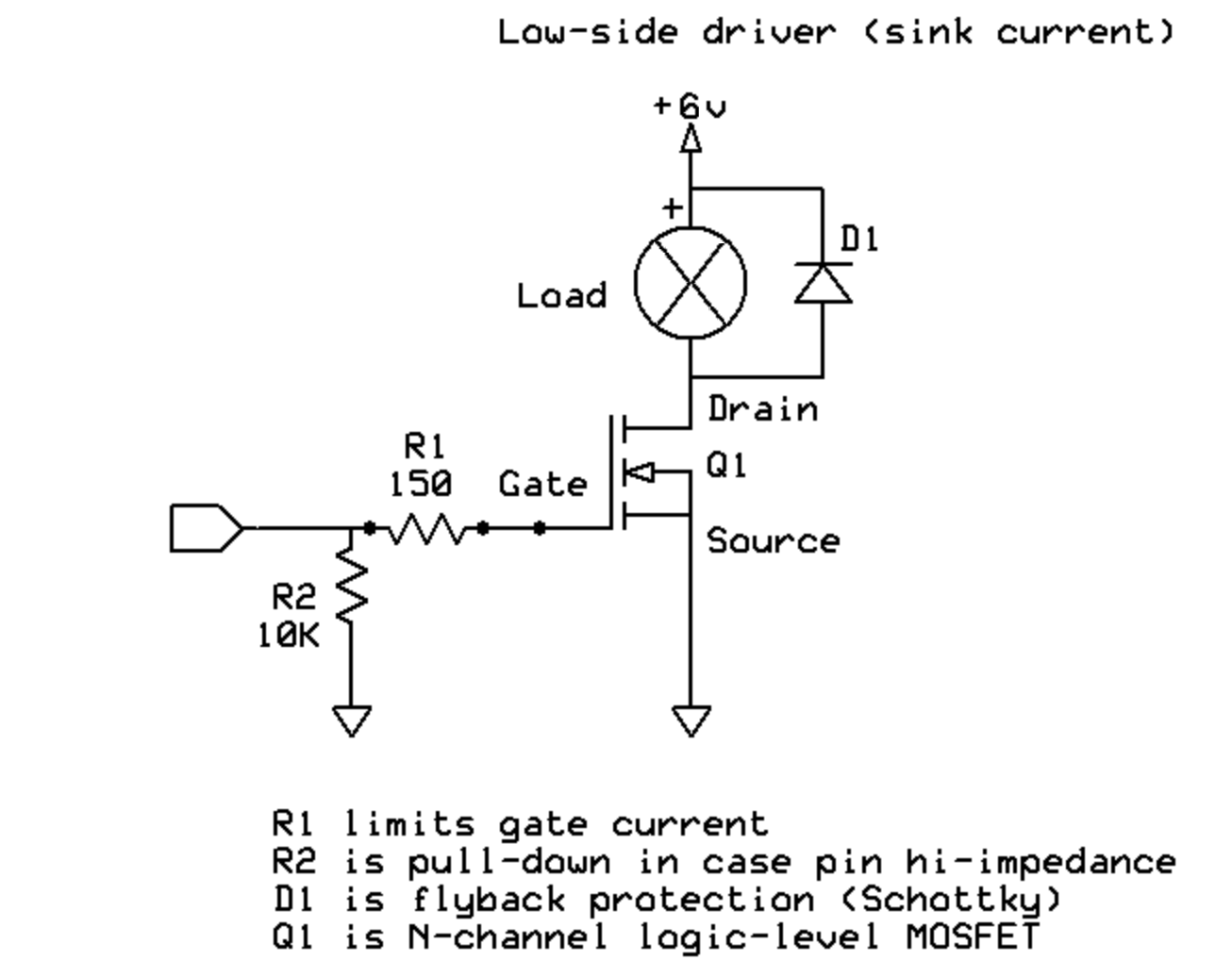
Posted at 2020-04-14 by @allObjects Take a look at @drazzy 's posts pertaining to MOS FETs How to use PICO with OLED and MOSFET? . He did extensive work and also sells on Tindie's https://www.tindie.com/products/drazzy/simple-sot-23-mosfet-six-pack-logic-level/ . All the FETs he uses have a lower range of GS voltage for on. Since power (current) is obviously not an issue you may add a BJT drives the FET and MDBT42Q drives the BJT (w/ inverse logic, of course). The resistor values may be halved in first schematics, since the source were 5 and 12 Volts. The second schematics has the resistors to limit the Gate current and make sure that with open drain / float output the FET is off ( @MaBecker , this time I was too lazy to go for character graphics... shoot and shop had to do it).Attachments: |
Beta Was this translation helpful? Give feedback.
-
|
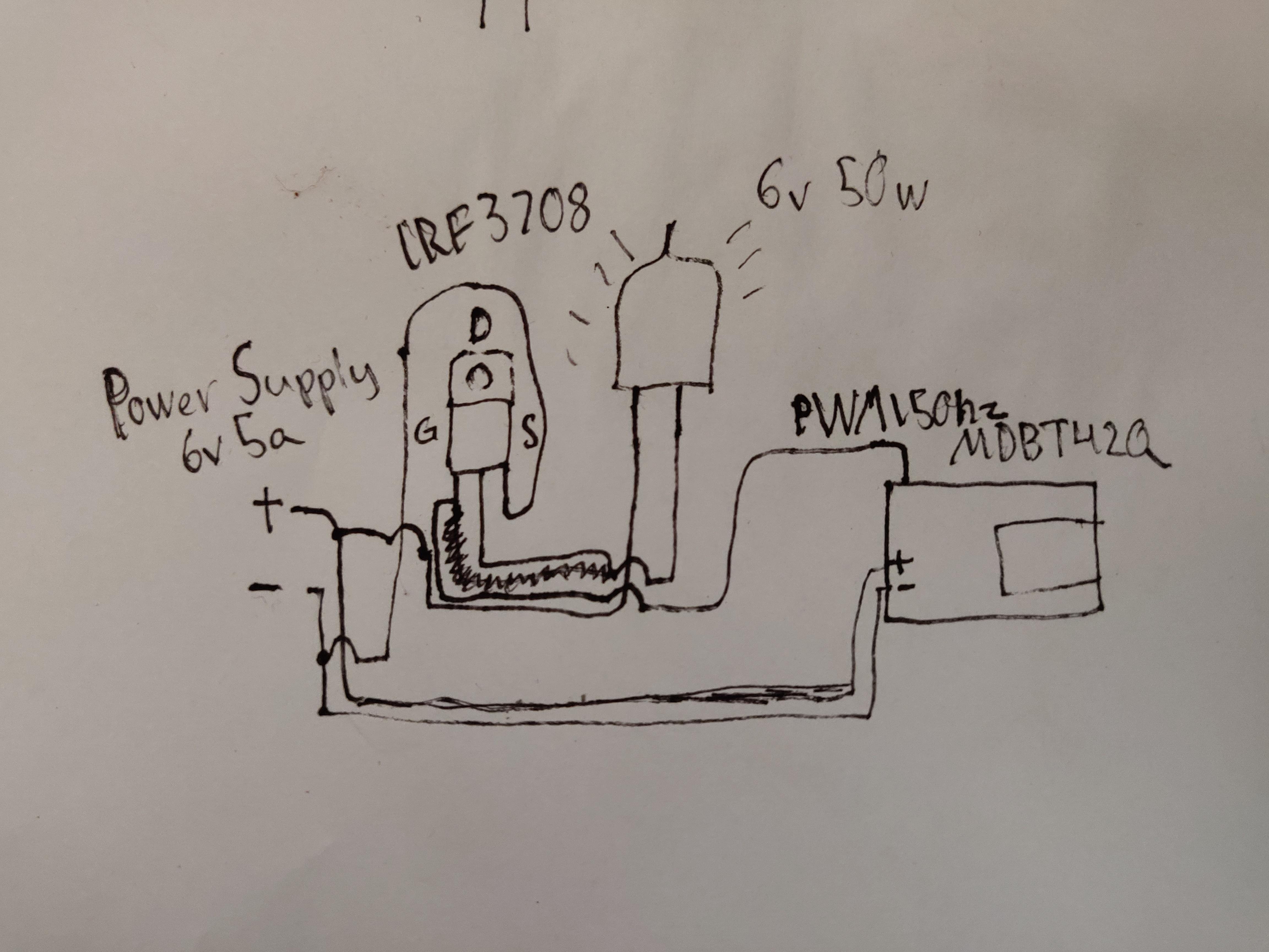
Posted at 2020-08-10 by DrAzzy How is it wired? I mean, I can take a guess that the answer is "wrong" but with a drawing of how it's wired up would help me be more specific. A hand-drawn picture, photographed with your cellphone is better than a fritzing diagram any day. Also, maybe a photo of the guts of the thing you're controlling just so I can give a quick reality check that it's what we think it is and should work how we think it should. |
Beta Was this translation helpful? Give feedback.
-
|
Posted at 2020-08-10 by DrAzzy Ugh, how did I end up here, 4 months late to the party.... blaaaah |
Beta Was this translation helpful? Give feedback.
-
|
Posted at 2020-08-11 by Gustav @drazzy Haha, thanks for the answer. I placed this project on the shelf over the summer, but you sparked my interest again. I will send a photo when i get the time. |
Beta Was this translation helpful? Give feedback.
-
|
Posted at 2020-08-11 by Gustav @drazzy Here is a quick and dirty paintingAttachments: |
Beta Was this translation helpful? Give feedback.
-
|
Posted at 2020-08-11 by Gustav lamp1Attachments: |
Beta Was this translation helpful? Give feedback.
-
|
Posted at 2020-08-11 by Gustav lampAttachments: |
Beta Was this translation helpful? Give feedback.
-
|
Posted at 2020-08-12 by DrAzzy Hmm... I would expect that to work, provided it really is 6v DC, not AC (if it was AC, you'd be able to tell pretty fast as the poor microcontroller you were powering with it failing with smoke. I would suggest a round of sanity checks - ie, wire it up, but without the microcontroller, manually connect gate to ground, light should now be off, connect to +6v, light goes on. Okay, is my code actually even turning on the pin, or is something silly wrong there? that kind of thing. |
Beta Was this translation helpful? Give feedback.
-
|
Posted at 2020-08-13 by Gustav Alright, i believe you can't drive this lamp with just 6v you need some type of waveform. |
Beta Was this translation helpful? Give feedback.
-
|
Posted at 2020-08-13 by Frida The first condition for making it work is that you |
Beta Was this translation helpful? Give feedback.
-
|
Posted at 2020-08-13 by Gustav What kind of transformer, could you supply me with an example ? |
Beta Was this translation helpful? Give feedback.
-
|
Posted at 2020-08-26 by DrAzzy Well, you said you were using the power supply it came with right? And that you had it hooked up to power the uC - and if it was an AC supply, and you had it hooked up to a microcontroller board, you would know, because the board would be emitting smoke and no longer responding to attempts at programming it |
Beta Was this translation helpful? Give feedback.
-
|
Posted at 2020-08-26 by Gustav @drazzy Well in the example i drew i didn't hook it up to the original power supply, but i included a image from the oscilloscope reading of the original power supply in my first post. |
Beta Was this translation helpful? Give feedback.
-
|
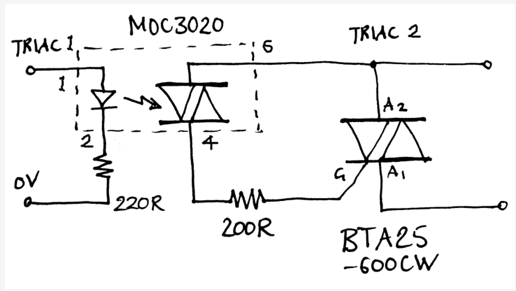
Posted at 2020-08-26 by @allObjects DC or AC? Shure, with DC, a MOSFET does the job, but it ties the mc power circuitry to the bulb circuitry. Using an opto driven driver triac and a load triac lets you use AC and you do not have to worry about cooling the rectifier etc... see this Arduino forum link: https://forum.arduino.cc/index.php?topic=460187.0 and also the attached datasheet for the MOC302X series of opto driven (driver) triacs. Attachments: |
Beta Was this translation helpful? Give feedback.
-
|
Posted at 2021-10-31 by user135957 @allObjects Hello everyone. I asked in another thread about a halogen bulb to light a projector. A The idea is to splice the halogen bulb on its own mounting into the wires for Thanks |
Beta Was this translation helpful? Give feedback.
-
|
Posted at 2021-10-31 by @allObjects @user135957, I would not run a 12V Halogen on a 24V supply... the bulb may immediately go or the power supply may tank... because current doubles and heats up the filament to the melting point. Finding a 12V 2A power supply is easy... for example https://www.amazon.com/ZOSI-2000MA-Adapter-Security-Surveillance/dp/B0147V94OA/ref=asc_df_B0147V94OA --- just search the internet for 12V 2A power supply. You can get also power supply that is adjustable: https://www.amazon.com/woajepu-Universal-Switching-Selectable-Electronics/dp/B07WWBB9DY/ref=sr_1_3 --- I have a similar and it works just fine - just make sure nothing turns (accidentally) the knob... put a duct tape over it after you set it... ;_) Btw, if you run (an older or not voltage regulated) projector, idle - no load - shows not what really what it will be... Another aspect: Powering on and off in 'rapid' succession such lamp is detrimental to its life span. I do not know the application / project, but you may consider a shutter rather than a short switch off, if this is what your project is about. A shutter you can build many ways... you can even take a relays/solenoid with something glued to the moving part for that, or a small stepper. |
Beta Was this translation helpful? Give feedback.
-
Posted at 2020-04-13 by Gustav
I am trying to power a low voltage tungsten halogen bulb using an MDBT42Q and an IRF3708 mosfet
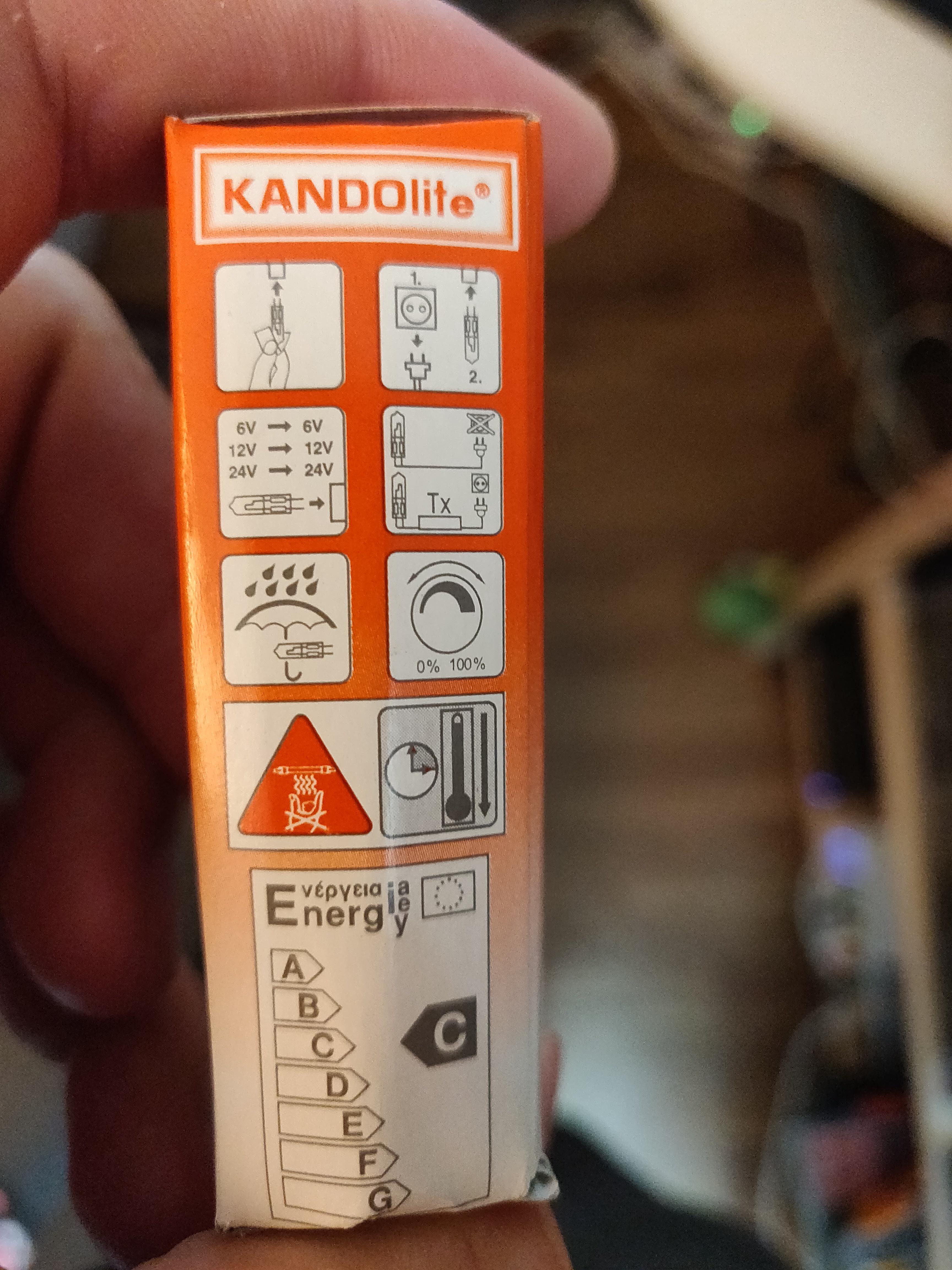
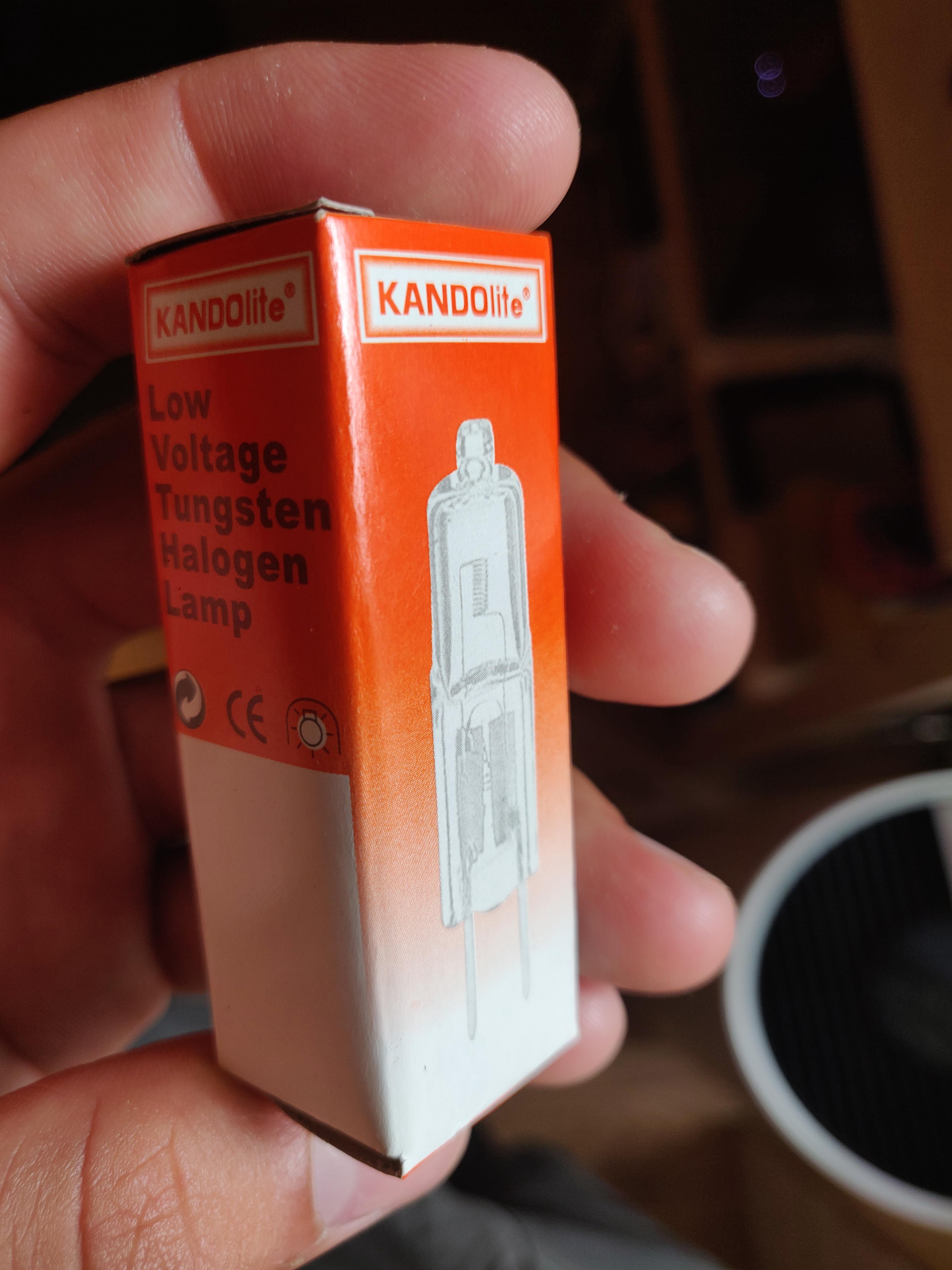
The lamp is a KANDOLite 6v 50w.
Im trying to replicate the signal coming from another driver that successfully powers the lamp.
The images with all statistics included is the original working solution.
There is one image when the lamp is connected and one without the load.
The image with fewer statistics is the signal from the drain pin in my solution.
Generating the pwm signal with MDBT42Q feeding it to the mosfet gate and powering the lamp with 6v. But no luck. Is it even possible to do this ?
Attachments:
Beta Was this translation helpful? Give feedback.
All reactions