-
Notifications
You must be signed in to change notification settings - Fork 70
Hardware
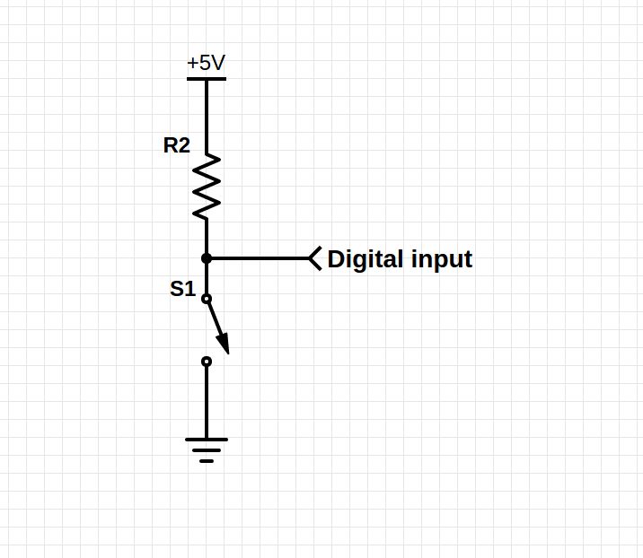
Connect one side of the switch to ground, and the other one to a digital input pin of the Arduino.
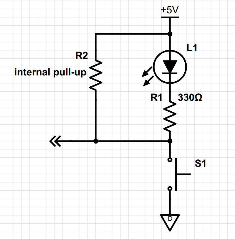
The Arduino has an internal pull-up resistor (R2), that connects the input to the 5V (3.3V) rail internally.
When the switch is open, there's 5V on the input, through the pull-up resistor. The Arduino registers this as a logical '1'. When the switch is closed, the input is connected to ground directly, so the input will be at 0V. This is registered as a logical '0'.

If you want to add LEDs that light up when a button is pressed, you can simply connect them in series with the switch. Remember to add a series resistor to limit the current.

Potentiometers and faders are hooked up as simple voltage dividers. You can read more on the Wikipedia page if you're not familiar with this principle.
On the schematic of a voltage divider above, there are two resistors. R1 is the resistance between the right pin of the potentiometer and the wiper (center pin), and R2 is the resistance between the left pin and the wiper. The sum of R1 and R2 is fixed. This is the value of the potentiometer, for a 50kΩ potentiometer, R1 + R2 = 50kΩ.
R1 and R2 vary from 0Ω to 50kΩ, depending on the position of the wiper.
To calculate the voltage on the wiper, the following formula is used:
As R2 varies from 0Ω to 50kΩ, the fraction varies from 0 to 1, and Vout varies from 0V to Vin. There's a linear relation between Vout and the position of the wiper. So by measuring Vout, the Arduino can determine the wiper position.
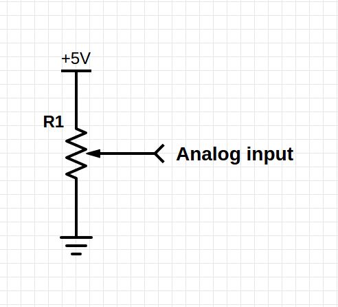
Connect the left pin of the potentiometer to ground, the right pin to 5V (3.3V), and the center pin (wiper) to an analog input on the Arduino:

First check the datasheet of your specific encoder, to see what the common pin is. If you don't have the datasheet, try connection it to two LEDs (+ series resistor). Connect the anodes of the LEDs to the +5V of an Arduino or other power supply, connect their cathodes via two resistors to two of the pins of the encoder, and connect the third pin to the ground of the Arduino or power supply. Now slowly turn the encoder. LED 1 should light up first, then LED2, then LED1 should go out, and finally LED2 should go out. The order of the LEDs lighting up should be like this: (○ ○) (● ○) (● ●) (○ ●) (○ ○).
If this is the case, the common, or C pin of the encoder is the one you connected to ground. If this is not the case, and the LEDs go on or off simultaneously, swap two wires and try again. (Don't worry, you will eventually find the right pin, there are only 3 possibilities.) The order of pin A and B doesn't matter.
Connect the common C pin to ground, and pin A and B to two interrupt-enabled input pins on the Arduino. They act like normal switches.
It's important to use interrupt pins, otherwise, the performance will be very poor, and you'll miss some clicks.
On an Arduino Uno, the only interrupt pins are 2 & 3.
On a Leonardo or Micro, you can use 0, 1, 2, 3 or 7.
On an Arduino Due or on a Teensy 3, you can use any two pins.
Connect the push buttons in a matrix as follows:

If you don't need to register multiple key presses at once, you can leave out the diodes.
