You signed in with another tab or window. Reload to refresh your session.You signed out in another tab or window. Reload to refresh your session.You switched accounts on another tab or window. Reload to refresh your session.Dismiss alert
I seem to have a peculiar issue with the SPI peripheral on stm32L100. For information, I am using a STM32l100RC discovery board. I am trying to interface a SPI Flash module, specifically the W25Q64.
I am working off from the beginning STM32, libopencm3 freertos by warren gay. I am not using the example code per say, just trying to get my hands dirty by using parts of his code to test that the device actually works and I am able to read/write to it. I am just using the barebones spi flash routines he has provided in the repo here
I am trying to read the JEDEC ID of the flash module. The flash module is supposed to return
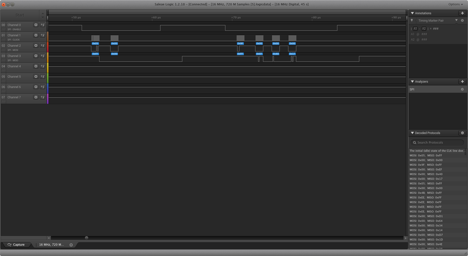
the manufacturer ID, memory type and capacity in that order, specifically the bytes EF, 40, 17 hex. I did verify that the modules work by trying them out with a arduino uno and here is the screenshot of the logic analyzer capture from the uno's capture
I tried to read the ID using the stm32l100rc discovery board and found that I am not able to get to the section where the command for reading the JEDEC ID is sent on the bus.
The code just is stuck in the w25_wait section.
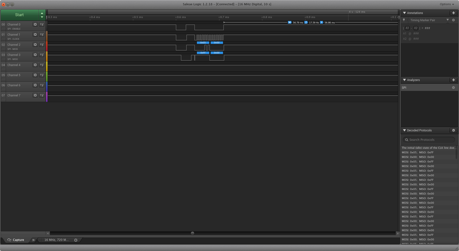
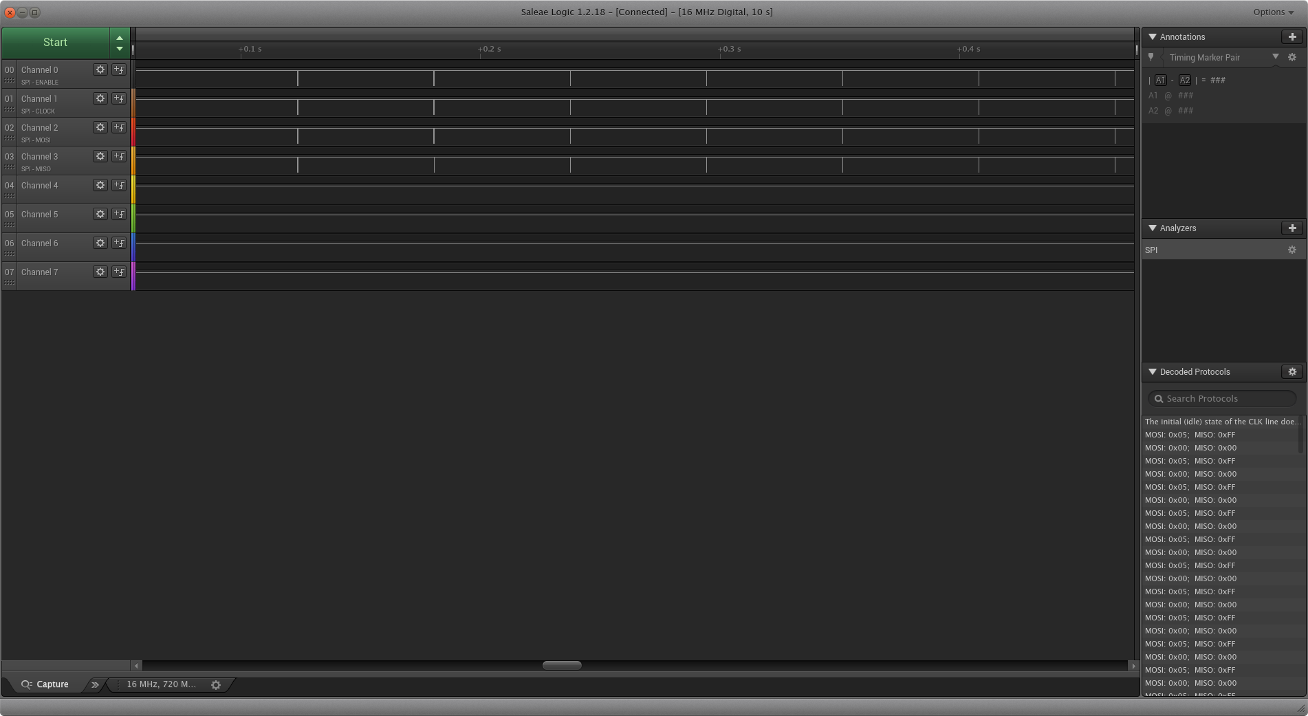
Here is the screenshot of the same
The code is just stuck in the wait routine.
Here is the relevant code
#include "libopencm3/stm32/rcc.h"
#include "libopencm3/stm32/gpio.h"
#include "libopencm3/stm32/usart.h"
#include "libopencm3/stm32/spi.h"
#include "delay.h"

#define W25_CMD_MANUF_DEVICE	0x90
#define W25_CMD_JEDEC_ID	0x9F
#define W25_CMD_WRITE_EN	0x06
#define W25_CMD_WRITE_DI	0x04
#define W25_CMD_READ_SR1	0x05
#define W25_CMD_READ_SR2	0x35
#define W25_CMD_CHIP_ERASE	0xC7
#define W25_CMD_READ_DATA	0x03
#define W25_CMD_FAST_READ	0x0B
#define W25_CMD_WRITE_DATA	0x02
#define W25_CMD_READ_UID	0x4B
#define W25_CMD_PWR_ON		0xAB
#define W25_CMD_PWR_OFF		0xB9
#define W25_CMD_ERA_SECTOR	0x20
#define W25_CMD_ERA_32K		0x52
#define W25_CMD_ERA_64K		0xD8

#define DUMMY			0x00

#define W25_SR1_BUSY		0x01
#define W25_SR1_WEL		0x02

static const char *cap[3] = {
	"W25X16",	// 14
	"W25X32",	// 15
	"W25X64"	// 16
};

static uint8_t
w25_read_sr1(uint32_t spi) {
	uint8_t sr1;

	spi_enable(spi);
	spi_xfer(spi,W25_CMD_READ_SR1);
	sr1 = spi_xfer(spi,DUMMY);
	spi_disable(spi);
	return sr1;
}

static uint8_t
w25_read_sr2(uint32_t spi) {
	uint8_t sr1;

	spi_enable(spi);
	spi_xfer(spi,W25_CMD_READ_SR2);
	sr1 = spi_xfer(spi,DUMMY);
	spi_disable(spi);
	return sr1;
}

static void
w25_wait(uint32_t spi) {
	uint8_t res= w25_read_sr1(spi);

	while ( (res & W25_SR1_BUSY) )
	{
		delay_ms(50);
		res = w25_read_sr1(spi);
	}
}

static uint16_t
w25_manuf_device(uint32_t spi) {
	uint16_t info;

	w25_wait(spi);
	spi_enable(spi);
	spi_xfer(spi,W25_CMD_MANUF_DEVICE);	// Byte 1
	spi_xfer(spi,DUMMY);			// Dummy1 (2)
	spi_xfer(spi,DUMMY);			// Dummy2 (3)
	spi_xfer(spi,0x00);			// Byte 4
	info = spi_xfer(spi,DUMMY) << 8;	// Byte 5
	info |= spi_xfer(spi,DUMMY);		// Byte 6
	spi_disable(spi);
	return info;
}

static uint32_t
w25_JEDEC_ID(uint32_t spi) {
	uint32_t info;

	w25_wait(spi);
	spi_enable(spi);
	spi_xfer(spi,W25_CMD_JEDEC_ID);
	info = spi_xfer(spi,DUMMY);		 // Manuf.
	info = (info << 8) | spi_xfer(spi,DUMMY);// Memory Type
	info = (info << 8) | spi_xfer(spi,DUMMY);// Capacity
	spi_disable(spi);

	return info;
}

static void
w25_read_uid(uint32_t spi,void *buf,uint16_t bytes) {
	uint8_t *udata = (uint8_t*)buf;

	if ( bytes > 8 )
		bytes = 8;
	else if ( bytes <= 0 )
		return;

	w25_wait(spi);
	spi_enable(spi);
	spi_xfer(spi,W25_CMD_READ_UID);
	for ( uint8_t ux=0; ux<4; ++ux )
		spi_xfer(spi,DUMMY);
	for ( uint8_t ux=0; ux<bytes; ++ux )
		udata[ux] = spi_xfer(spi,DUMMY);
	spi_disable(spi);
}


int main(void) {
	char array[] = "Hello World!!";
//Always set the clock for the ports and peripherals first

//Select HSICLK with PLL as sysclock source
// Sysclock frequency is 16 Mhz

	rcc_clock_setup_hsi(&rcc_clock_config[RCC_CLOCK_VRANGE1_HSI_RAW_16MHZ]);

//Enable GPIOC Peripheral clock
	rcc_periph_clock_enable(RCC_GPIOC);
//Output mode, no pull ups or pull down
	gpio_mode_setup(GPIOC, GPIO_MODE_OUTPUT, GPIO_PUPD_NONE, GPIO8 | GPIO9);
//Set GPIO8 and clear GPIO9 to see toggle
	gpio_set(GPIOC, GPIO8);
	gpio_clear(GPIOC, GPIO9);

//Sequence of steps for SPI transactions
//Enable the clocks for the pin ports and peripheral for SPI
//Setup pins for the alternate functions
//PA4 = SPI1_NSS, PA5 = SPI1_SCK, PA6 = SPI1_MISO, PA7 = SPI1_MOSI
//reset the SPI peripheral
//initialize the SPI peripheral with the peripheral, clock, clock polarity,
//clock phase, data frame format, frame format
//set nss management to software otherwise SPI peripheral wont work
//enable the SPI peripheral
//send or read data using spi_send or spi_read functions

	rcc_periph_clock_enable(RCC_GPIOA);
	rcc_periph_clock_enable(RCC_SPI1);
	gpio_mode_setup(GPIOA, GPIO_MODE_AF, GPIO_PUPD_NONE, GPIO4 | GPIO5 | GPIO7);
	gpio_mode_setup(GPIOA, GPIO_MODE_AF, GPIO_PUPD_NONE, GPIO6);
	gpio_set_af(GPIOA, GPIO_AF5, GPIO4 | GPIO5 | GPIO7);
	gpio_set_af(GPIOA, GPIO_AF5, GPIO6);
	spi_reset(SPI1);
	spi_init_master(SPI1, SPI_CR1_BAUDRATE_FPCLK_DIV_64, SPI_CR1_CPOL_CLK_TO_0_WHEN_IDLE, SPI_CR1_CPHA_CLK_TRANSITION_1, SPI_CR1_DFF_8BIT, SPI_CR1_MSBFIRST);

	spi_disable_software_slave_management(SPI1);
	spi_enable_ss_output(SPI1);
	while (1)
	{
		gpio_toggle(GPIOC, GPIO8 | GPIO9);
		uint8_t index = 0;

		w25_wait(SPI1);
		spi_xfer(SPI1, 0x9F);
	 	uint8_t result1 = spi_xfer(SPI1, 0x00);
		uint8_t result2 = spi_xfer(SPI1, 0x00);
		uint8_t result3 = spi_xfer(SPI1, 0x00);
		spi_disable(SPI1);
		delay_ms(500);
	}

	return 0;
}
I apologize for the length of the code.
As I ve said earlier, the code is simply stuck in the w25_wait routine. it never progressess beyond.
I tried debugging further and it looks like that the condition (res & W25_SR1_BUSY)
in the w25_wait function always returns true. This is because the previous function invocation of uint8_t res= w25_read_sr1(spi);
in the line above always returns 1.
And this is the relevant snipper for the w25_read_sr1
But the logic analyzer capture shows that the data being returned is 0x00 not 0x01.
I would be extremely grateful if you can help me identify the issue to where and what I am doing wrong.
I am more inclined to believe it is because I goofed up something in the initialization and/or the handling. But it is more or less a adapted version of the book's example code from the bluepill to the stm32l100rc.
Thank you in advance.!! :-)
The text was updated successfully, but these errors were encountered:
Hello,
I seem to have a peculiar issue with the SPI peripheral on stm32L100. For information, I am using a STM32l100RC discovery board. I am trying to interface a SPI Flash module, specifically the W25Q64.
I am working off from the beginning STM32, libopencm3 freertos by warren gay. I am not using the example code per say, just trying to get my hands dirty by using parts of his code to test that the device actually works and I am able to read/write to it. I am just using the barebones spi flash routines he has provided in the repo here
https://github.com/ve3wwg/stm32f103c8t6
I am trying to read the JEDEC ID of the flash module. The flash module is supposed to return

the manufacturer ID, memory type and capacity in that order, specifically the bytes EF, 40, 17 hex. I did verify that the modules work by trying them out with a arduino uno and here is the screenshot of the logic analyzer capture from the uno's capture
I tried to read the ID using the stm32l100rc discovery board and found that I am not able to get to the section where the command for reading the JEDEC ID is sent on the bus.


The code just is stuck in the w25_wait section.
Here is the screenshot of the same
The code is just stuck in the wait routine.
Here is the relevant code
I apologize for the length of the code.
As I ve said earlier, the code is simply stuck in the w25_wait routine. it never progressess beyond.
I tried debugging further and it looks like that the condition
(res & W25_SR1_BUSY)in the w25_wait function always returns true. This is because the previous function invocation of
uint8_t res= w25_read_sr1(spi);in the line above always returns 1.
And this is the relevant snipper for the w25_read_sr1
But the logic analyzer capture shows that the data being returned is 0x00 not 0x01.
I would be extremely grateful if you can help me identify the issue to where and what I am doing wrong.
I am more inclined to believe it is because I goofed up something in the initialization and/or the handling. But it is more or less a adapted version of the book's example code from the bluepill to the stm32l100rc.
Thank you in advance.!! :-)
The text was updated successfully, but these errors were encountered: