-
Notifications
You must be signed in to change notification settings - Fork 13
4DEBSD
Please note that this program is very much in development.
In the TEM community, the term 4D-STEM refers to a collection of imaging modalities that are carried out by post-processing of a 2D set of 2D CBED patterns (hence the 4D in the label). In the EBSD community, we also have a 2D set of 2D EBSD patterns, so we should be able to post-process those images in various ways, i.e., a 4D-EBSD approach. The EM4DEBSD program represents an attempt to create such a post-processing program.
This implementation of 4D-EBSD relies on a two-step process:
- first a virtual detector is defined and the complete EBSD data set is convolved (using fft's) with this detector; this step generates a new data file (HDF5 of the type EMEBSD32f);
- the second step has multiple options to generate output images starting from the data file generated in the first step:
- a regular array of virtual detectors is extracted from the file and turned into a 2D array of virtual images; this is useful to get an overall impression of the data set and to identify potentially interesting locations;
- an individual detector location can be selected on the master pattern and the pattern orientations (from an indexing step) are then used to determine the exact location of the virtual detector in each diffraction pattern; this eliminates orientation-dependent contrast and ideally results in clean defect images.
Prior to executing the EM4DEBSD program, the user must have several files available:
- an experimental EBSD data set in any of the commonly used vendor formats.
- an EMsoftOO master pattern file computed for the experimental accelerating voltage and sample tilt angle; this also implies that the crystal structure file be available.
- a master pattern image file, obtained from the master pattern file using the EMgetMP program.
- an EMsoftOO dictionary indexing output file with refined orientations, i.e., the result of running the EMFitOrientations program on the EMDI dot product file. At the present development stage (April 2024) this program does not work with indexing output files from spherical indexing, .ang files, or .ctf files; at some point in the future, those formats may be included as well.
- it may also be useful to run the EMdpextract program on the dot product file to extract a variety of image files and inverse pole figure maps.
A virtual detector is a square array of dimension VDsize by VDsize in which each pixel is assigned a weight in such a way that the sum of all weights equals unity. This detector array is then convolved with each individual EBSP using fft operations; background subtraction in the form of a high-pass filter is also performed at the same time. The filtered EBSPs are then written to a new output file in the EMEBSD32f HDF5 format.
Currently, there are three options for the virtual detector:
- a 2D uniform (flat) detector with equal weights of value 1/VDsize^2 in all pixels;
- a 2D Gaussian detector with standard deviation VDSD;
- a 2D Hann window with default parameter VDHannAlpha set to 0.5, so that the weights go to zero all around the edges of the detector array.
The three detectors are shown in the figure below for VDsize=13, VDSD=2.5 and VDHannAlpha=0.5.

As with most EMsoftOO programs, the input parameters of this program are organized as a name list and a template name list file can be generated using the standard -t command line flag:
EM4DEBSD -tThis then generates the template file in the currrent folder. The content of the file is as follows:
 &EBSD4Ddata
! template file for the EM4DEBSD program
!
! The values below are the default values for this program
!
!=====================================
! Pattern Data
!=====================================
! height of inverse pole figure in pixels
 ipf_ht = 100,
! width of inverse pole figure in pixels
 ipf_wd = 100,
! define the region of interest;  leave all at 0 for full field of view
 ROI = 0 0 0 0,
! number of pattern pixels along x and y
 numsx = 0,
 numsy = 0,
! minimum distance from center of pattern at which to start ignoring virtual detector positions [pixels]
! leave at zero if no cutoff is to be used
 radiuscutoff = 0.0,

!=====================================
! if doconvolution = .TRUE., then perform a full data set convolution and store the
! results in the HDF5 file convolvedpatternfile [relative to EMdatapathname]
! else we interrogate the convolvedpatternfile
!=====================================
 doconvolution = .FALSE.,
 convolvedpatternfile = 'undefined',

!=====================================
! Virtual Detector Parameters
!=====================================
! virtual detector type:  'Flat', 'Gaus', 'Hann', 'Array'
 VDtype = 'Flat',
 ! this parameter is only used for the Array representation
 normalize = 'all',  ! or 'pat' for individual pattern-by-pattern normalization
! virtual detector reference: 'EBSP', 'MPat'
 VDreference = 'EBSP',
! coordinates of the sampling point from which the EBSP is used to define the detector position
 EBSPlocx = 0.0,
 EBSPlocy = 0.0,
! center coordinates of virtual detector
! in terms of EBSD pattern coordinates for VDreference='EBSD'
! in terms of master pattern coordinates for VDreference='MPat'
 VDlocx = 0.0,
 VDlocy = 0.0,
! square virtual detector size (should be odd numbers of the form 2*n+1 !)
 VDsize = 5,
! Gaussian virtual detector standard deviation
 VDSD = 2.5,
! Hann window alpha parameter
 VDHannAlpha = 0.5,
! stepsize in pixels for VDtype='Array' mode
 VDstep = 8,

!###################################################################
! Input File Parameters
!###################################################################
!
! name of datafile where the patterns are stored; path relative to EMdatapathname
 exptfile = 'undefined',
! input file type parameter: Binary, EMEBSD, EMEBSD32i, EMEBSD32f, TSLHDF, TSLup2,
!                            OxfordHDF, OxfordBinary, BrukerHDF, NORDIF
 inputtype = 'Binary',
! here we enter the HDF group names and data set names as individual strings (up to 10)
! enter the full path of a data set in individual strings for each group, in the correct order,
! and with the data set name as the last name; leave the remaining strings empty (they should all
! be empty for the Binary and TSLup2 formats)
 HDFstrings = '' '' '' '' '' '' '' '' '' '',
! name of the dot product file [relative to EMdatapathname]
 dotproductfile = 'undefined',

!=====================================
! Master pattern file (for a future implementation)
!=====================================
! the following parameter MUST be set if VDreference = 'MPat'
 masterfile = 'undefined'

!=====================================
! Output files
!=====================================
! name of virtual detector image file
 virtualimagefile = 'undefined',

!=====================================
! number of threads (default = 1)
!=====================================
 nthreads = 1,
/The first step in using this program to create virtual detector images consists of configuring the input name list file so that the detector convolution and background subtraction process is properly executed. If we use a Hann virtual detector with the default parameter setting and a size of VDsize=11, the following parameters need to be set (note that all comment lines as well as unused parameters have been removed):
 &EBSD4Ddata
 ipf_ht = 500,
 ipf_wd = 500,
 ROI = 0 0 0 0,
 numsx = 256,
 numsy = 256,
 doconvolution = .TRUE.,
 convolvedpatternfile = 'path/filename.h5',

 VDtype = 'Hann',
 VDsize = 11,
 VDHannAlpha = 0.5,

 exptfile = 'path/filename.extension',
 inputtype = 'Binary',
 HDFstrings = '' '' '' '' '' '' '' '' '' '',
 dotproductfile = 'path/filename.h5',

 nthreads = 12,
 /
The program will read the experimental patterns as well as a few parameters from the dot product file (output of the EMDI program) to generate a new HDF5 file (convolvedpatternfile) in the EMEBSD32f format. The experimental file can be in any of the supported file formats. The output file may be larger than the original input file since the pattern intensities are stored as 4-byte floats. Note that the type of virtual detector must be set in this first run of the program.
There are three distinct ways to generate virtual detector images:
- using a stationary virtual detector;
- using an orientation-adaptive virtual detector;
- using a 2D array of stationary virtual detectors.
Each method is described in more detail below and generates a tiff output file containing the virtual detector image or images. More methods may be added in the future. Note that for each of these methods, the doconvolution parameter in the name list file must be set to .FALSE., and the convolvedpatternfile must be set to the proper pre-computed file generated in section 4.
In the sections below, we will make use of the Ni data set that has been used in many publications so far. The data set can be downloaded from here (select the Ni.tar.gz file as well as the ReadMe.txt file for detailed information). We will assume below that all the files mentioned in the section above are available to the user, and that the convolvedpattternfile has been created. This data set has IPF map dimensions of 186x151 pixels.
A stationary virtual detector is a detector that is located in the same pixel position on every EBSD pattern in the dataset; this mode can be selected by setting the VDreference parameter to EBSP, and also setting the EBSPlocx, EBSDPlocy, VDlocx, and VDlocy parameters. The first two coordinates can be set by the user by taking any of the images generated from the dot product file by the EMdpextract program and picking a point in the region of interest with respect to the top left corner. The program will then generate a file called EBSPpositions.tiff which shows the EBSP corresponding to that location, as well as the location of the virtual detector within that EBSP (which corresponds to the other two coordinates VDlocx and VDlocy with respect to the lower left corner). That same pixel location is then used for all the EBSD patterns to generate a single virtual detector image that is stored in the file defined by the virtualimagefile parameter.
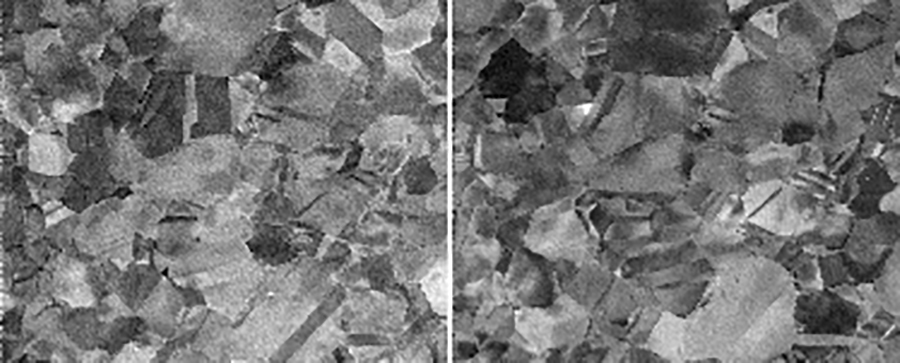
The figure below shows two different images generated using the VDreference='EBSP' option for (VDlocx, VDlocy)=(7,28) (left) and (40,20) (right). Note that every single EBSP has these locations so that there are no undefined pixels (as opposed to the situation in the next example).

An orientation-adaptive virtual detector is a detector that is located at a particular point in the master pattern; this mode can be selected by setting the VDreference parameter to MPat. As before, the EBSPlocx and EBSDPlocy parameters are set to select a particular EBSP. The VDlocx and VDlocy parameters on the other hand are determined with respect to the center of the master pattern (Northern hemisphere). The program will generate a file called MPpositions.tiff that shows the selected point as well as all symmetrically equivalent points; it also generates a EBSPpositions.tiff file which shows all the equivalent virtual detector positions that fall within the pattern. The virtual detector closest to the center of the EBSP is then selected to generate the virtual detector image. Note that the pixel location of that virtual detector is potentially different in each EBSP. The net result of this approach is that most of the orientation intensity variations that arise with the stationary virtual detector image are eliminated. Depending on the camera length (or z-star), it is possible that the selected orientation is not present in some of the diffraction patterns (or is located at a distance larger than radiuscutoff from the center of the pattern); in that case, the grain or grains for which this occurs will be left blank in the output image.
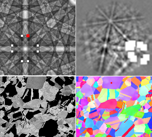
The example below shows the general process. First, select a location in the IPF map (IPF-Z map in this case); we picked the location indicated with the red square in the center-top purple grain, i.e., (EBSPlocx,EBSPlocy)=(86,15) from the top left corner. Then pick a location in the master pattern (top left image); we picked the point indicated by the red square, (VDlocx, VDlocy)=(7,30) with respect to the center of the master pattern, and the program filled in the equivalent locations. Running the program then generates the diffraction pattern on the top right with superimposed equivalent virtual detedctor locations (the larger square is the one closest to the center of the diffraction pattern), as well as the virtual detector image in the lower left. Note that those grains for which the virtual detector is too far from the center of the pattern (for radiuscutoff=28 pixels) are black.

This mode requires that the VDtype parameter be set to Array; the VDstep parameter then determines how many virtual detectors will be used to generate the output image mosaic. The number of virtual images along horizontal and vertical directions corresponds to the EBSP dimensions divided by the VDstep value (integer division). The location of the first virtual detector will be the position (VDstep/2,VDstep/2) and then the remaining detectors are positioned at integer multiples of VDstep in each direction. The output image can be very large, depending on the size of the IPF map and the number of virtual detectors. In general, when looking at the 2D array image as a whole, there is some resemblance of the intensity distribution to an actual EBSP; zooming into individual patterns near Kikuchi bands can then provide information about interesting virtual image features that could be studied using the orientation-adaptive virtual detector approach.
The example below for the Ni data set shows the virtual detector array for VDstep=8 and VDsize=7 (Hann window used to compute the convolvedpatternfile). Since the original IPF map has dimensions 186x151, and 60/8=7 (integer division) so the virtual detector array image has dimensions 1302x1057.

Wiki pages are maintained by M. De Graef; they are part of the EMsoftOO package and fall under the same copyright (BSD2).
Information for Users
SEM Modalities
- Monte Carlo Simulations- EBSD Master Pattern Simulations
- EBSD Depth Master Pattern Simulations
- TKD Master Pattern Simulations
- ECP Master Pattern Simulations
- Overlap Master Patterns
- EBSD Pattern Simulations
- ECP Pattern Simulations
- TKD Pattern Simulations
- Dictionary Indexing
- EBSD Spherical Indexing
- EBSD Reflector Ranking
- Ion-induced Secondary Electron Master Pattern
- ECCI Defect Image Simulations
- 4DEBSD
TEM Modalities
- HH4- PED
- CBED Pattern Simulations
- STEM-DCI Image Simulations
- EMIntegrateSTEM utility
Utility Programs
- EMConvertOrientations- EMDisorientations
- EMHOLZ
- EMKikuchiMap
- EMOpenCLinfo
- EMZAgeom
- EMcuboMK
- EMdpextract
- EMdpmerge
- EMdrawcell
- EMeqvPS
- EMeqvrot
- EMfamily
- EMGBO
- EMGBOdm
- EMgetEulers
- EMgetOSM
- EMlatgeom
- EMlistSG
- EMlistTC
- EMmkxtal
- EMorbit
- EMorav
- EMorient
- EMqg
- EMsampleRFZ
- EMshowxtal
- EMsoftSlackTest
- EMsoftinit
- EMstar
- EMstereo
- EMxtalExtract
- EMxtalinfo
- EMzap
Complete Examples
- Crystal Data Entry Example
- EBSD Example
- ECP Example
- TKD Example
- ECCI Example
- CBED Example
- Dictionary Indexing Example
- DItutorial
Information for Developers