This repository contains manufacturing details as related to smart energy meter, details such as hardware design, web software, firmware, exterior casing STL files, rationale behing design, how-to document to guide a skilled user to replicate every part of the smart meter is available in the repository.

The open-source smart meter development has four main parts to it as highlighted below:
The circuit was designed on Kicad free and open-source PCB design software while the enclosure design was done using Fusion 360 software.
PCB fabrication involves putting together the physical components that makes up the smart meter. The PCB features a 2layer design incorporating CICADA GSM module for communication while the enclosure offers a minimalistic IP 51 design according to IEC metering enclosure design standard.
The firmware code was written in Arduino IDE using C++, while the web front end was written majorly in HTML and CSS while the back end was written majorly in PHP. Links to all these codes are here. Thingsboard API was used to view meter parameters such as energy, credit.
After putting the hardware and software together, we needed to validate the performance of the smart meter and ascertain its accuracy. Due to varying tolerances of used components, it is vital to perform a calibration exercise. This is used to correct any errors due to varying tolerances. Further details including source code, schematics, and manufacturing files can be found in the EnAccess github repository
The documentation folder contain all information as related to manufacturing the smart energy meter, information such as Api documentation , rationale behind design, calibration report, trouble shooting manual, bill of material, datasheet for all components used.
The firware code folder contain the firmware code written in C++ on Arduino platform, the folder also contain the library files used in the code.
The meter hardware design folder contain the Kicad design file, gerber manufacturing file, exterior casing manufacturing files, design images.
This folder contain the web demo video to guide a developer developer on the functionality of the web software.
This folder contain the web software codes used. the link to the web demo is : https://paygotesting.000webhostapp.com
The voltage regulation stage contains the 7805IC to regulate the voltage from the SMPS power supply to 5V as this is the safe voltage level to power the microcontroller, also this stage contains the LM350IC to regulate the SMPS power sully to 4V to power the GSM module.

The analog front end chip (AFE) is a metering IC suitable for a class1 and class2 accuracy meter and fit for use according to the relevant metering standard as specified by IEC. it is used in this design to measure power, voltage, current, power factor e.t.c.

The SMPS stage converts the AC input voltage supplied into the meter to 12V DC to power the internal electronics circuit.

The master of this stage is the microcontroller(STM32f103ccu8) popularly known as bluepill, it fethes outputted meter values from the AFE chip via the USART communication interface, it also communicate with the webpage via the Cicada GSM module and sends neccesary meter parameters to the RS232 port, this stage also interface with other hardware pheripherials such as keypad, buzzer, magnetic latching relay, LED, LCD.

This document summarizes the manufacturing guide to enable a skilled person to manufacture the smart energy meter. the foldered is structured as highlighted below including informations available in each folder.
The documentation folder is sub-divided into different folder containing relating documents as named in the folder title.
The firmware code folder contain the Firmware code and all library used in the smart meter design.
The meter hardware design folder contain all relating files as relating the manufacturing meter hardware such as design images, exterior casing design file, PCB CAD design file, GERBER file.
The meter web software folder contain the web software code, from the front end, backend, images, styling file e.t.c.
The web software is split into different parts as highlighted below. i. Extraction of zip file from Github. ii. Creating database. iii.Linking Thingsboard public link to webpage.
The web software can be replicated by any developer by downloading the code file from https://github.com/EnAccess/OpenSmartMeter/tree/main/Web%20software . after the code is downloaded, developer will need to host the web on a hosting platform.
The database schema file can be downloaded from the Github link provided below
https://github.com/EnAccess/OpenSmartMeter/blob/main/Documentations/Web%20Software%20and%20API%20documentation/meter.sql for testing purpose, next user can assign a meter number as desired from MT1 to MT99990 and insert into the meter Database column for meter number.
Developer need to change password and database name in web code to same password and database name as created by developer to enable access to the database.
After Thingsboard page is setup, developer make the data available by changing the privacy setting from private to public, next the public link is copied to the Thingsboard column specified in the database for each user.
The hardware is splitted into different parts as highlighted below. a.Extracting manufacturing file. b.Soldering/assembling PCB. c.Firmware flashing to microcontroller.
The first step is to extract the manufacturing/production file from Github in the link provided below https://github.com/EnAccess/OpenSmartMeter/tree/main/Meter%20hardware%20design/production%20file, the zip file is sent to a PCB manufacturing company for the board to be manufactured. The manufactured PCB is shipped back to the design engineer.
The PCB is assembled, soldered according to the components value as labeled on the silkscreen layer of the PCB board. The turn ratio of the ferrite core transformer is given below in figure 1. Feed back turn = 7turns. Input (100v - 270v) = 53 turns. Output(12v) = 10 turns.

Figure 1 : Transformer configuration/turn diagram.
The meter calibration is done after the meter PCB component is fully assembled alongside exterior casing. Step 1 : Calibrating voltage and current The design engineer proceed to calibrate the voltage, current. The voltage and current is calibrated by calculating the value measured by meter as compared to the true value measured by a test bench, the excel sheet available in the link provided below is used to calibrate the voltage and current by inputting the measured and actual values of voltage and current in the appropriate cell of the excel calculator. https://github.com/EnAccess/OpenSmartMeter/blob/main/Documentations/Datasheet/Energy%20setpoint%20calculator.xlsx, after this is done, the hex code gotten is written to the neccesary registers of Ugain, IgainN in the SAM_UART.cpp library provided in the link below. https://github.com/EnAccess/OpenSmartMeter/blob/main/Firmware%20code/Library/SamATM90E26_library after this is done, the checksum2 value displayed on the LCD screen while the meter is starting up is written to the CSTwo register in the SAM_UART.cpp library, after this is done, design engineer re-uploads the code to the chip and all measuring parameter is correct.
Note : A meter test bench is needed to know the true value of voltage and current to be calibrated into the meter.
Step 2 : setting impulse rate The impulse rate is changed by writing to PLconstH and PLconstL in the SAM_UART.cpp library after inputting the correct value of Un = 240V (measured voltage). Ib = 5A (base current). GL = 1 (line current circuit gain). VL = 21.3(sampling voltage of current circuit in MV). VU = 260 (sampling voltage of voltage circuit in MV). MC = 2000 (impulse rate) Note: the impulse is 1000, however the value is multiplied by 2 due to current scaling.
Note : The values specified above is the values used according to the resistor value used in meter PCB.
Step 3 : calibrating impulse
A test bench is required to measure the % error of the meter, after this is done the design engineer can input the error gotten into the excel calculator provided in the link below.
https://github.com/EnAccess/OpenSmartMeter/blob/main/Documentations/Datasheet/Energy%20setpoint%20calculator.xlsx, after the error is calculated, the design engineer write the value gotten for Lgain and Igain to the neccesary register in the SAM_UART.cpp library, then the new value of checksum1 is rewritten to the library for the meter to blink properly.
After developer is done assembling the components on the PCB, it is advisable to test the PCB first by connecting the battery to the battery connector to test if all connection is correct or not, if all connection is correct the meter LCD will display, then meter boot and try connecting to internet before the LCD is turned off due to unavailability of mains and to preserve battery life.
Connect the input of the meter through an incandescent bulb without any load to the meter to prevent the components from going up in smoke if there is a short or mis-soldering, if the meter PCB is faulty the incandescence bulb will light up brightly, if all is ok, the meter will start up however the bulb may light up a little bit if all is ok.
the first thing to do is to Install STM32 Add-on to Arduino IDE by following the steps below.
https://github.com/stm32duino/BoardManagerFiles/raw/master/STM32/package_stm_index.json


Download and install STM32CubeProg from ST.com: https://www.st.com/en/development-tools/stm32cubeprog.html


Make sure the boot 0 jumper pin on the board is set to 1 (programming mode) while uploading the boot loader. Once the boot loader is flashed this pin can be changed back to initial position (operating mode).
Set the Upload method to STM32CubeProgrammer (Serial)


There are some hardcoded variables in the firmware code which needs to be in sync with the values used on the web server e.g token, API key,web server. sample pictures of variables to be changed is shown below.


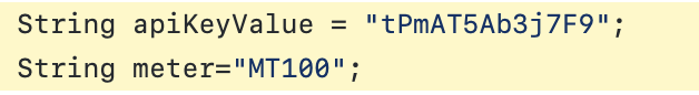
More information as relating to the implementation of the firmware with the software is available in https://github.com/EnAccess/OpenSmartMeter/blob/main/Documentations/Web%20Software%20and%20API%20documentation/API%20Documentation.pdf
There are some variables that needs to be changed in the backend codes, the database details need to be changed to the databases details as created on the webserver. More information as relating to the implementation of the software/API deployment is available in https://github.com/EnAccess/OpenSmartMeter/blob/main/Documentations/Web%20Software%20and%20API%20documentation/API%20Documentation.pdf
