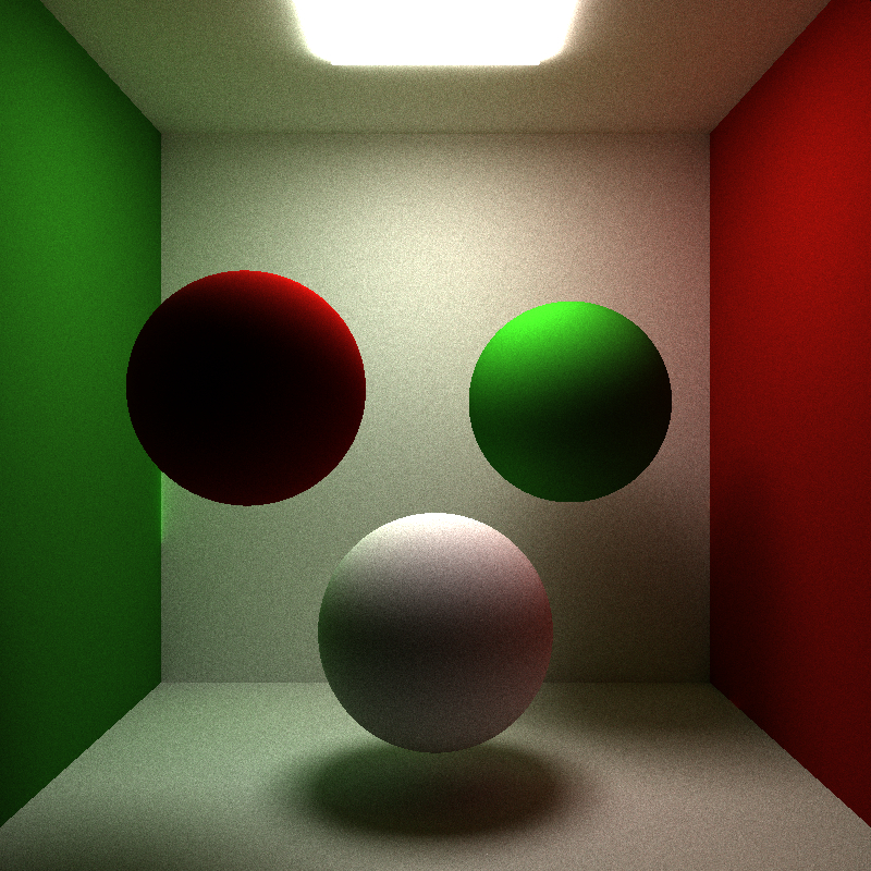
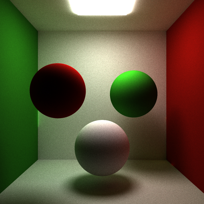
This project is a CUDA-parallelized Monte Carlo path tracer implemented for CIS 565 during my fall 2014 semester at Penn. Given a scene file that defines a camera, materials, and geometry, my path tracer is capable of rendering images with full global illumination, including realistic diffuse surfaces, color bleeding, caustics, area lights, and soft shadows. Additionally, my path tracer supports Fresnel refractions for glass materials and texture mapping for both spheres and cubes.
My path tracer is parallelized per ray rather than per pixel. At the start of each iteration, one ray is generated for each pixel in the image buffer and stored in a ray pool. At each trace depth (basically every time a ray intersects geometry), rays are checked to see if they should be retired from the ray pool. In my path tracer, rays are retired if they (A) do not intersect with any piece of geometry in the scene, or (B) intersect with a light source. A retired ray is removed from the ray pool and will not be considered during future kernel calls to the GPU.
A per-ray parallelization scheme such as this prevents unwanted cases where some rays in a warp become inactive at a low trace depth while neighboring rays remain active until the max trace depth. In these circumstances, valuable GPU processing time is wasted on inactive rays that no longer contribute to the final rendered image result.
To support a per-ray parallelization scheme, stream compaction is used to cull retired rays from the ray pool. I use the thrust parallel algorithms library (https://code.google.com/p/thrust/) to perform my stream compaction. After all computations have been performed for rays at a certain trace depth, the ray pool is checked for retired rays (identified by a boolean member attached to each ray), and if a retired ray is found, I remove it from the ray pool with thrust's remove_if method. Then, during the next trace depth iteration, I send the current ray pool to the GPU which no longer contains any retired rays.
Currently, my path tracer supports sphere and cube geometry and ideal diffuse, perfectly specular, and glass materials. In the future, I plan to support arbitrary mesh objects and more complex BRDF models.
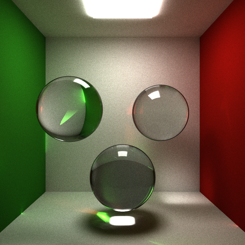
As can be seen in the image below, my path tracer supports glass materials. Transmission direction and probability of reflection and refraction are computed using the well-known Fresnel equations. An interesting implementation detail to note is that my parallelization scheme does not support recursion. This is due in part to my decision to never spawn new rays inside CUDA kernels which stems from my decision to initialize the ray pool with a fixed max size. In traditional path tracers and ray tracers, radiance at a point is often computed through recursion. This is especially important for refractive materials because when a ray intersects a refractive surface, often two rays are emitted from the intersection point--one reflective ray and one refractive ray. All these rays contribute to the final computed pixel color.
In my path tracer, when rays intersect with a refractive surface, I use Fresnel's equations to determine the probability that a ray will either reflect or refract, but never both. In the future, I would like to explore methods in which I can retain my per-ray parallelization scheme while also dynamically spawning new rays when rays intersect refractive surfaces.
In the image below, some green artifacts can be seen (most prominently on the left side where the green and white walls meet). I suspect these artifacts are caused by an integer overflow when seeding my random number generators because they only appear after a large number of iterations (~4000). However, I have not spent much time looking into this issue, so I cannot be sure of the cause.
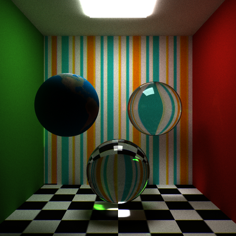
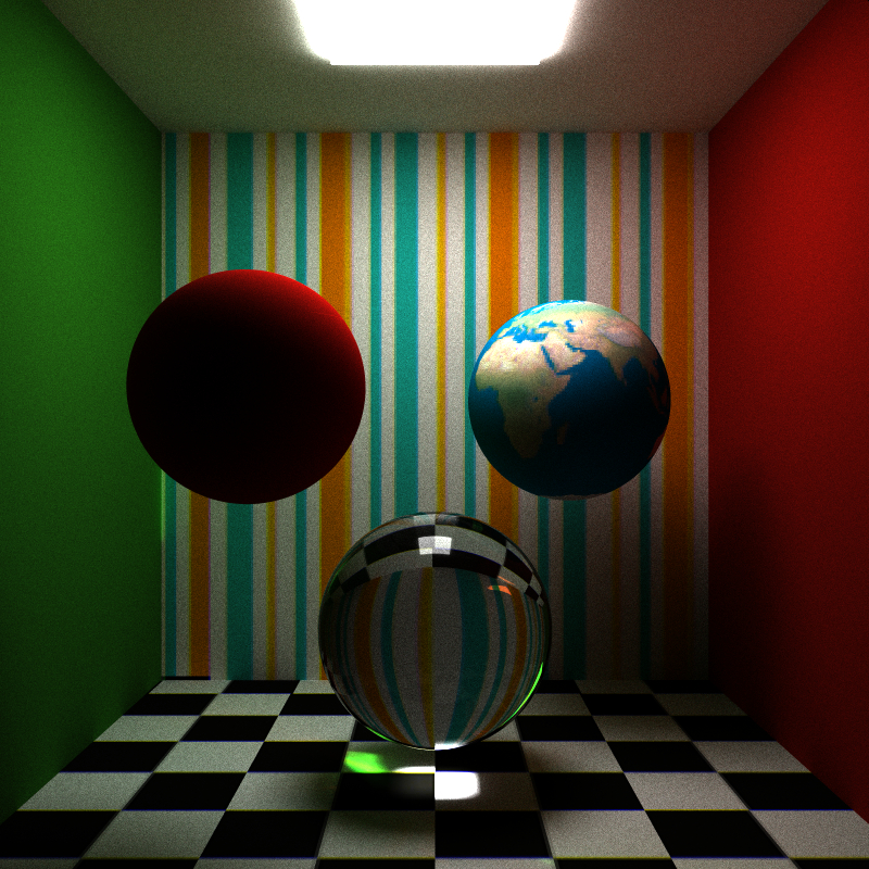
I implemented texture mapping for spheres and cubes. When a piece of geometry with an applied texture is intersected, the intersection point is transformed to object-space where the uv-coordinates ([0, 1]) for the image are computed. These uv-coordinates are then multiplied by the texture dimensions to determine the desired pixel within the texture. It is this texture pixel's RGB information that is used when computing radiance instead of the geometry's material RGB.
For me, the most difficult part of implementing texture mapping was getting the texture information onto the GPU. First, I tried passing in a list of data structures representing each texture, but I ran into problems allocating memory on the GPU since each texture could theoretically have different dimensions, and thus have different memory requirements. To use a list of data structures, I needed to define a fixed, uniform maximum texture resolution for each texture. This ensured that each texture structure had the same memory requirements, and made GPU memory allocation straightforward. However, defining a maximum texture resolution was too limiting.
Instead, I opted to "flatten" all my textures into a single array of glm::vec3s representing RGB values at runtime. Additionally, I created an array of ints at runtime that stored the dimensions for each texture as well as the starting index within the array of RGB values for each texture. Through my work implementing texture mapping, I've learned that while CUDA supports multidimensional data and complex data types, it is most happy with flat data and primitive data types, and I was happy to honor its preferences.
Currently, my textures do not support any kind of transparency, but I would like to utilize image alpha channels in the future.
Supersampled anti-aliasing is a method to remove jagged edges that involves averaging multiple samples for every pixel where each sample (ray) originates from a different location from within a pixel (not just from the pixel's center). With a path tracer, since many rays (100+) must be processed for each pixel in order to create a physically plausible image, supersampled anti-aliasing comes for "free". Each ray shot through a pixel during one iteration of the path tracing algorithm is jittered, or moved ever-so-slightly, within the bounds of that pixel in relation to the ray sampled for that pixel during the previous iteration, and then the results for every iteration are averaged together. This results in edge pixels getting smoothed with their neighboring pixels which softens hard edges.
I say supersampled anti-aliasing comes for free to a path tracer, because very little overhead is required to take advantage of it. This is in contrast to other renderers, such as ray tracers, where only a single ray is required for each pixel to generate a complete image. For a ray tracer to take advantage of supersampled anti-aliasing, additional rays need to be generated for each pixel that are not needed for basic image generation. As a result, supersampled anti-aliasing in a ray tracer increases runtime considerably.
In my implementation, I discretize each pixel into a pre-defined number of rows and columns, and at each iteration I sample a pixel at a random location within one of the cells formed by the grid of rows and columns. The sub-pixel cell I sample changes each iteration, and I cycle through the cells linearly. The results of my implementation can be seen in the two images below. The first image does not use anti-aliasing. The second image does. The benefits of anti-aliasing in these images are most evident in the base of the green wall and in the outline of the red sphere against the white wall behind it.
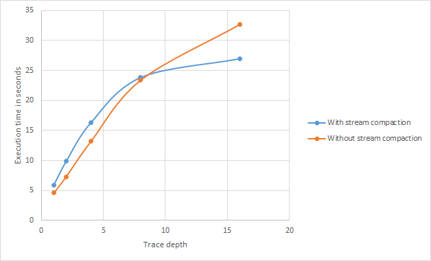
Below, I ran a few performance tests to measure the usefulness of stream compaction in my implementation. The tests were performed over 100 iterations with a block size locked at 128 threads-per-block with a varying trace depth (the number of times a ray was allowed to bounce in the scene). As can be seen in the scatter plot, no stream compaction outperforms stream compaction until a trace depth of 7-8 is reached. After that, stream compaction far outperforms no stream compaction.
Considering what I wrote above about how stream compaction in concert with a per-ray parallelization scheme prevents rays of wildly varying "number-of-trace-depths-until-retirement" to share a warp on the GPU (see section labeled "Parallelization scheme" above for more information), these results make sense. With a low trace depth, the largest disparity between rays that retire at a trace depth of one vs. those that retire at the maximum trace depth is relatively small. As the maximum trace depth grows, this potential disparity grows as well, which results in more wasted GPU resources as kernel calls become filled with retired rays that can no longer contribute to the final render.
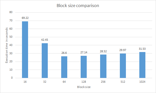
The second chart visualizes the optimum block size for my path tracer. As with the previous tests, these tests were performed over 100 iterations. As can be seen in the chart, a block size of 64 or 128 is recommended for highest performance.
My next steps for this project include implementing:
- Direct lighting samples so my renders converge more efficiently.
- Bump maps.
- Image-based emittance.
- Depth of field.
- An obj loader.
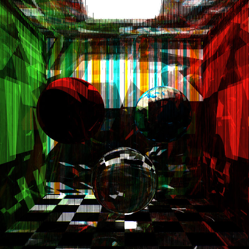
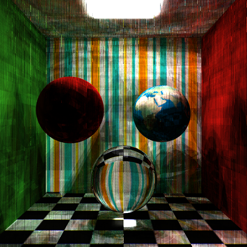
During development, I noticed that restricting random number generation in nonsensical ways resulted in some interesting abstract image creation. The first image below is no way physically correct, but it is my favorite image generated with my path tracer so far.
I want to give a quick shout-out to Patrick Cozzi who led the fall 2014 CIS 565 course at Penn, Harmony Li who was the TA for the same course, and Yining Karl Li who constructed much of the framework my path tracer was built upon. Thanks guys!
