-
Notifications
You must be signed in to change notification settings - Fork 0
Electronic_SCL_Std

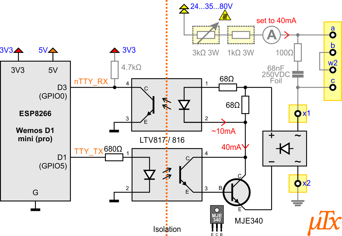
This example is more simple but fit all you need to communicate with a teletype without a FSG (dialing device). It is designed to use common components which should be found in every makers stock.
In this example the teletype current of 40mA is provided by a resistors in line (potentiometer) and have to be calibrated to 40mA. In stead of making he power supply yourself, you can use a (historic) teletype test device and put this circuit in line at any position of the loop.
The ESP part and the teletype part are fully isolated from each other.
If need a relay to power on the teletype motor, use relay transistor parts from schematic above.
Status: tested and working

Note: TXD have to be NOT inverted and RXD have to be inverted in software
Note: The bridge rectifier can be skipped if you are sure you do not change poles!
- any with Vrrm>100V and I>100mA
- PC817, LTV817 (Vce=35, CTR>50%)
- PC816, LTV816 (Vce=80, CTR>50%)
- any opto coupler with CTR>50%
- PC817, LTV817 (Vce=35, CTR>50%)
- PC816, LTV816 (Vce=80, CTR>50%)
- any opto coupler with CTR>50% and Vce includes voltage source
Note: The transmitter voltage tolerance (Vce) must be higher than the power supply voltage
- MJE230 (Vce=300V, Ic=500mA)
- BD139 (Vce=80V, Ic=1.50A)
- any NPN transistor with hfe>25, Ic>200mA and Vce includes voltage source
Note: The transistor voltage tolerance (Vce) must be higher than the power supply voltage


