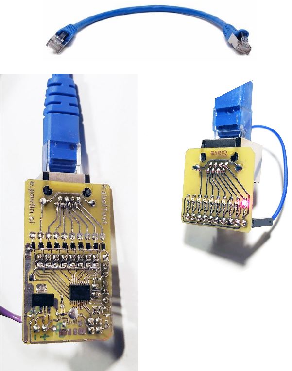
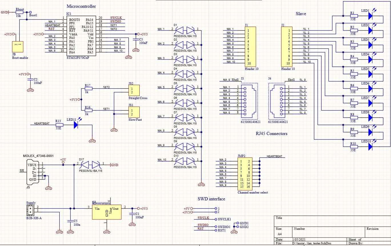
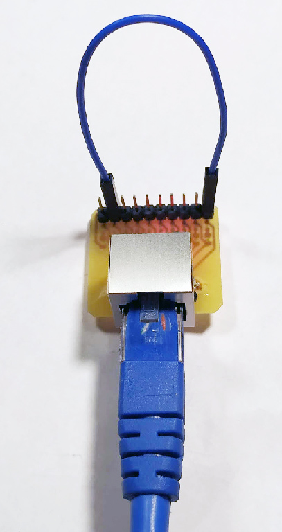
This is simple cable testing tool for checking your cables (e.g. ethernet patch cables or house installation). Complete tester consists of two modules and tested cable. Master (left) module is on the left. It is connected to the power supply (battery or wall adapter). Slave (right) is passive and has only LEDs.
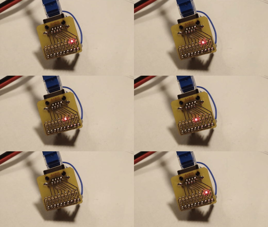
If cable is OK, the leds should run in ordered sequence:
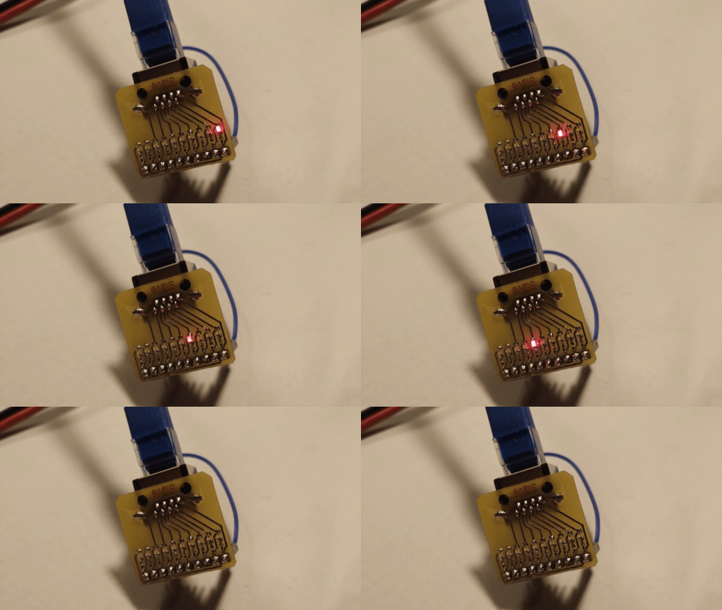
Youtube video: https://youtu.be/-cTYe7WnijU
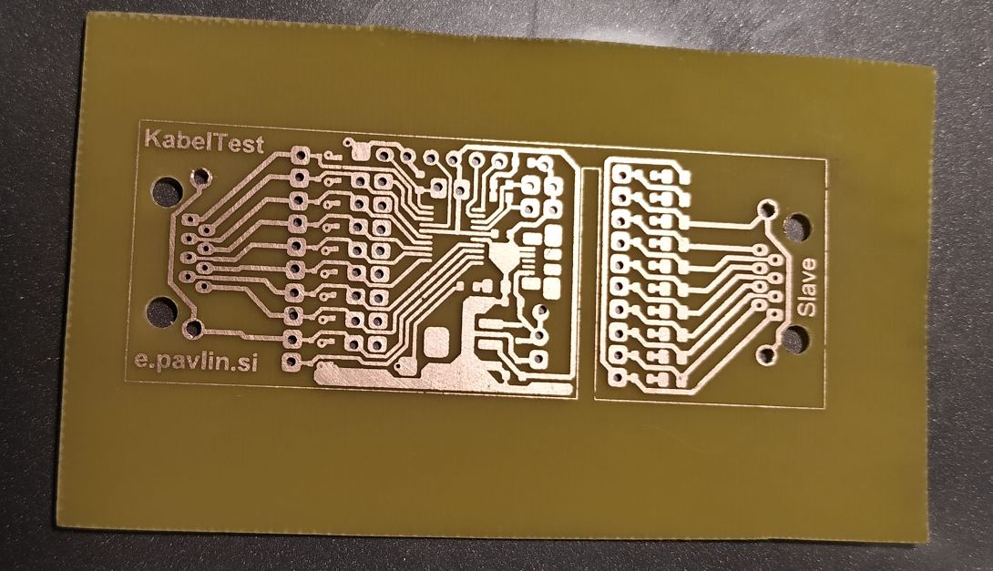
PDF for home made PCB with toner transfer (multiple and single PCB) is available here.
Initial project is prepared with free keil uVision for stm32f0 family.
There is no need to use any IDE or programming adapter to download the firmware. It can be done via serial bootloader. Detailed instructions are here.
Work in progress.
There are several jumpers available to control operation of the tester.
JS1 selects the speed of sequence. When jumper is attached, the sequence is slow or fast when removed:
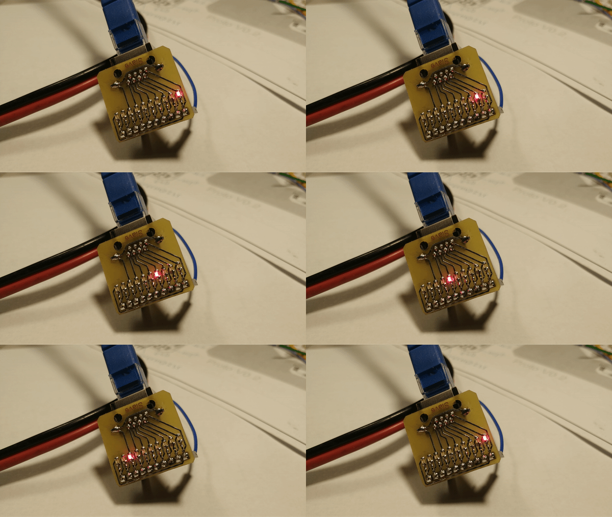
JS2 select sequence: When not present the sequence is "normal": Ch1, Ch2, ... Chn. When Jumper is present, the sequnence is set for cross linked cable (useful for testing crosslink patch cables).
The cable tester has 10 channels. The channel sequence can ruun from 2 to maximum 10 channels. Jumper JMP2 defines number of channels. Inserted jumper bridge defines where the sequence will stop. When bridge is inserted between pins 13 and 14 (Channel 8), the sequence will run up to 8th channel. Example of the sequence when jumper is placed on channel 5:
PCB for slave device is prepared for RJ45 female connector. There are 10 pins for custom connectors available. When testing less than 10 wires, a jumper must be placed between last+1 channel and first channel to provide proper connection for LEDs.
Example for testing ethernet patch cable (8 channels active): jumper should be placed between pin 1 and pin 9 on the jumper J4 (slave device):
