-
Notifications
You must be signed in to change notification settings - Fork 3
Long Range Comms.
The RFD 900x Radio Modems are a long-range wireless communications solution. They are replacing the built-in Odin chips to allow the GNSS Modules to communicate over a much longer distance. See the rangecheck for information on the out-of-the-box range.
The user manual (at the time of writing) for the modems can be found here.
- Blinking Green: Active and searching for another radio to link with
- Solid Green: Active and linked to another radio
- Blinking Red: Blinks on packet transfer
- Solid Red: Ready to accept a firmware update
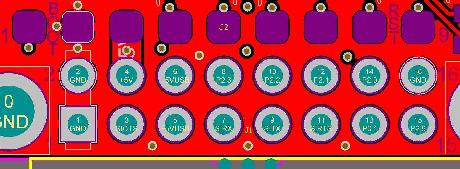
The pinout of the RFD 900x is as shown in the image below:
Please note that the radios should link to each other out-of-the-box and operate at a baudrate of 57600.
There are three officially supported firmware versions. The default version is peer to peer, in which two radio modems (nodes) link and maintain bi-directional communication. The other firmware versions allow a more complicated network to be set up (with 3 or more nodes) but require more configuration, such as setting node IDs. Note that if a second rover is to be set up, the firmware must be switched to one of these other networks.
When using the peer to peer (Sik) firmware, there are two usual ways of communicating with the modems: through AT/RT commands and through APM Planner (a.k.a the ArduPilot Mission Planner).
The parameters that were changed for this particular setup was to change the serial baudrate to 115200 baud. This is to match the output baudrate of the GNSS modules and the rate itself is only secondary. The network ID ("netid") was also changed (just in case); the two modems must have the same network ID.
For usage and configuration using AT/RT commands, please refer to this document.
For usage and configuration using APM Planner, please refer to this guide.
For the greatest range, the antennas should be arranged at 90°. Alternatively, higher-powered antennas can be used and each antenna can be assigned to TX and RX individually.
For the antennas to reach their full potential, a separate power supply line should be used to power the modems that provide ample current to power them. Computers are not always able to provide the proper wattage.
Apart from this, simply connect the grounds of the modems to the grounds of the GNSS modules and their UART TX/RX in an appropriate configuration.
The rangecheck was performed with both modems using the dipole antennas (included in the startup kit) at a 90° angle.
| Antenna | Antenna Config | Incline | Obstructions | Baudrate | Max Range |
|---|---|---|---|---|---|
| Inc. Dipole | 90° | Flat | None | 115200 | ____m |
| Inc. Dipole | 90° | Flat | Scattered | 115200 | ____m |
| Inc. Dipole | 90° | Sloped | None | 115200 | ____m |
| Inc. Dipole | 90° | Sloped | Scattered | 115200 | ____m |
