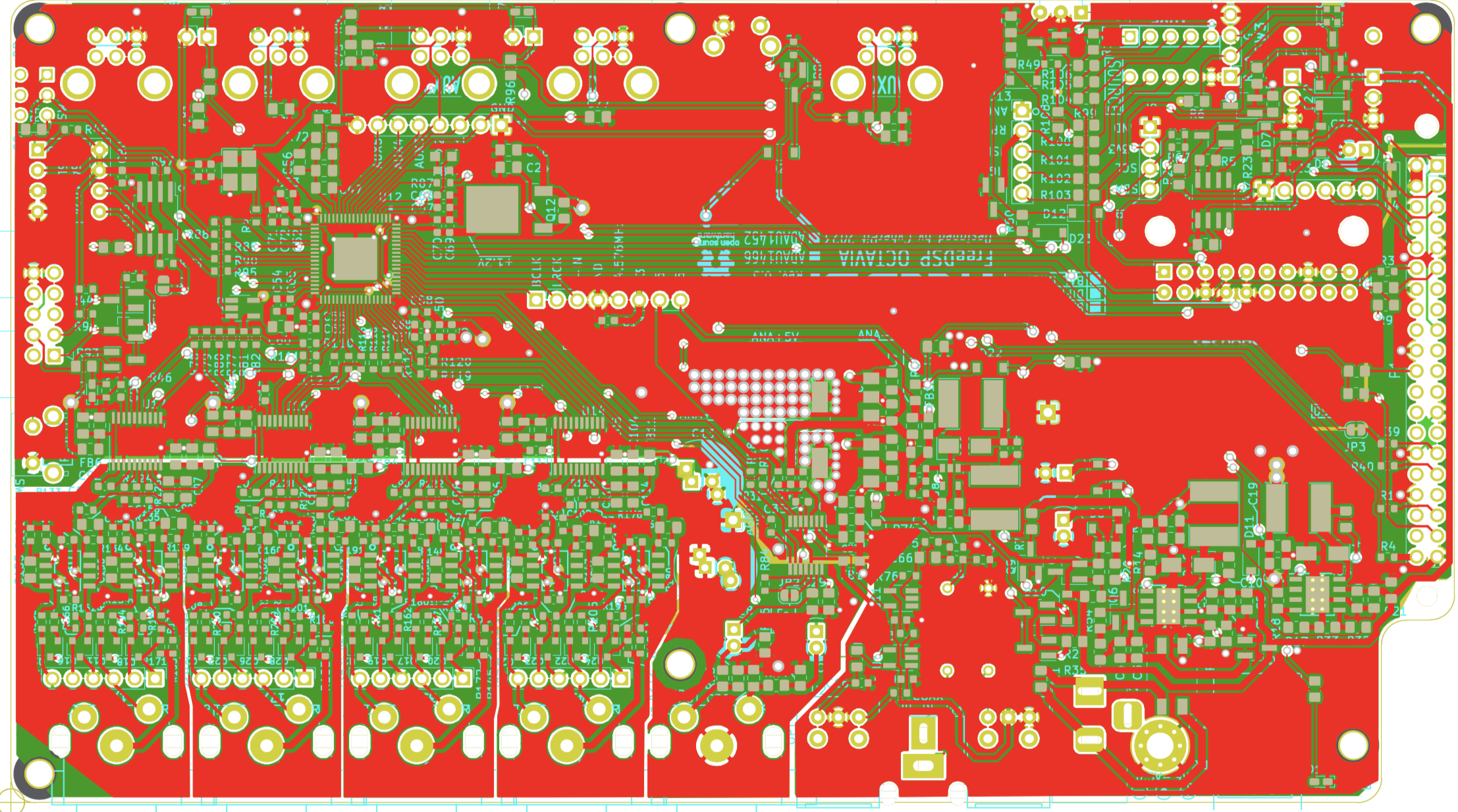
-
Notifications
You must be signed in to change notification settings - Fork 0
Change Order List
- Modify the board type conversion method. (Easily convert from Differential Output to Standard version(Unbal))
- Changed D4 connection point. (Ease for I2C header debugging)
- Add an AGND fill plane on the bottom layer.
- No functional change from ver1.1
- Modify the land of FL1 as ACM9070.
- Add an optional feature for the "YORK" USB Audio/I2C Interface module.
The YORK module will work as a USB-I2S Audio interface and USBi. It's a physically compatible-sized board with Amanero Combo384.

You can change the I2C routing from RPi to YORK by change connection of JP4 and JP5.
- Fixed value and JLPCB part# of R57, and R59.
- No Gerber/Drill/Placement Data Changes.
Version 1.00 Board PCBA Image

- Change the RCA-pin jack from model MJ-518A to RCJ-2223. (Upside down of L/R)
- Fixed the muting logic control PCB trace at the USB position.
- Add Connection Jumper R61 between the AGND and DGND.
Version 0.33j Board PCBA Image

- Change the Board Layers from 2 to 4.
- Change the voltage regulator IC for Analog +5V and +3.3V rails(U3/U7 changed from AZ1117 to LM317)
Heaksink is not required anymore even if using the 9V Power Supply. - Apply new Differential/Balanced Output Driver Circuit.
- Add an Ele-Cap Near the positive power rail decoupling C13.
- Changed the muting logic control design at the USB position.
- Carefully re-designed PCB Analog part traces to increase the Audio performance.
Version 0.3 Board Image

Additional two internal layers are used for power distribution and individual signal return grounds.
Separate channel pair layout and slit regional solid fill design will improve channel separation and decrease distortion performances.
Version 0.2 Board Image

- Recommended Supply Voltage was changed from DC12V to 7.5V (DC6.5V can be up to 9V, Lower is better to reduce the heat radiation) The consuming current of supply capacity requires 2A or More. (At least 1A or more is required even if without using Raspberry-pi) Here is an excellent choice.

- R100, R101, R102, R103 (330R -> 1k) To dim the LED brightness
- R7, R33 (1k -> 3.3k) _To expand the range of working power supply voltage
- R76 (4.7k -> 330R) To decrease the gain
- SW1, SW7 (PTS645V) Changed to have a fixing tabs
-
J13 pin1 net ("+5V" -> "+3.3V") Always on and decreases the position LED brightness
-
PCM5012A XSMT control circuit design has changed
-
SW1, SW7 (PTS645V) for PCM5012A XSMT control circuit design had changed
-
J13 pin1 net ("+5V" -> "+3.3V") Always on and decreases the position LED brightness
-
Pinout of J8 changed (0V,VCC,SCL,SDA) To fit the small OLED Display
Intend to use the following kinds of devices.Candidate OLED modules...


-
J7 (4pin 2.54mm Header) Extention header for Power indicator RAGB LED
Anode Common RGB LED will fit for external Power status indicator.

Pin order is RED - Anode - GREEN - BLUE (Bottom to up) -
J9 (3pin 2.54mm Header) Extention header for MP6/MP7 indicator LED
-
D22, D23 (1N4148W) used for XSMT control citcuit
-
Q32 (AO3401A) used for XSMT control citcuit
-
R50 (10k) used for XSMT control citcuit
- U3, U7 (Thermal Relief Added)
- D3 (Moved between SW2 and SW3)
- C13 moved away from the heat source